© 2021 Radiodetection Ltd 24
Linear current loss may naturally occur along the pipeline
due to the age of the pipe and coating conditions.
6.7 ACVG Surveys
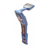
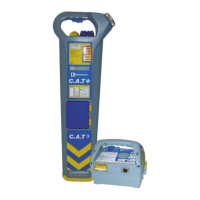
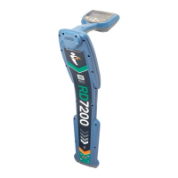
The accessory A-Frame is used with the PCMx locator to
precisely pinpoint coating defects and isolation faults.
An Alternating Current Voltage Gradient, (ACVG), survey
measures the leakage current in the vicinity of the pipeline to
assess the coating condition, and pinpoint coating defects. An
advantage of this survey method is that it can be done on a
route parallel to the pipe. For example, it may be done on a
pavement or grass verge parallel to a pipe running below a
road surface. It requires the use of the PCMx A-Frame
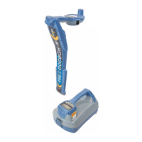
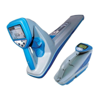
accessory in addition to the PCMx locator and transmitter.
The A-Frame spikes need to make good electrical contact
with the ground, preferably with damp, conductive earth. If
the ground is dry or the ground is concrete it is advisable to
pour water around the spikes or fit a piece of sponge to each
spike and soak with water to increase the conductivity
between the A-Frame spikes and the ground.
The PCMx locator display indicates direction to the fault,
using the fault find direction arrows, and this makes fault
position easy to locate.
The PCMx also displays the dB microvolts reading across
the A-Frame spikes, and this allows a comparison to be
made between different faults to determine the most
severe. This numeric value along with the direction arrows
can be stored in the PCMx, recalled, and uploaded via the
PCM Manager application.
Method
After obtaining PCMx current loss using the 4Hz results,
decide which sections of the pipeline require fault find
survey.
1. Connect the transmitter to the pipeline and ground.
2. Set the PCMx transmitter to either ELCD or
LFCD mode.
3. Connect the A-frame to the PCMx locator via the
accessory socket, and turn on the locator.
4. The PCMx will default to ACVG mode and an A-
frame symbol will be displayed.
5. Choose an appropriate starting point for your
survey. If a suspected fault location has been
identified from a previous ACCA survey, begin the
survey approximately 60 feet, (20 meters) from
the suspected fault.
6. Place the A-frame spikes in the ground above, or
parallel with, the pipe. Position the green spike

 Loading...

