PCMx Operation Manual
© 2021 Radiodetection Ltd 25
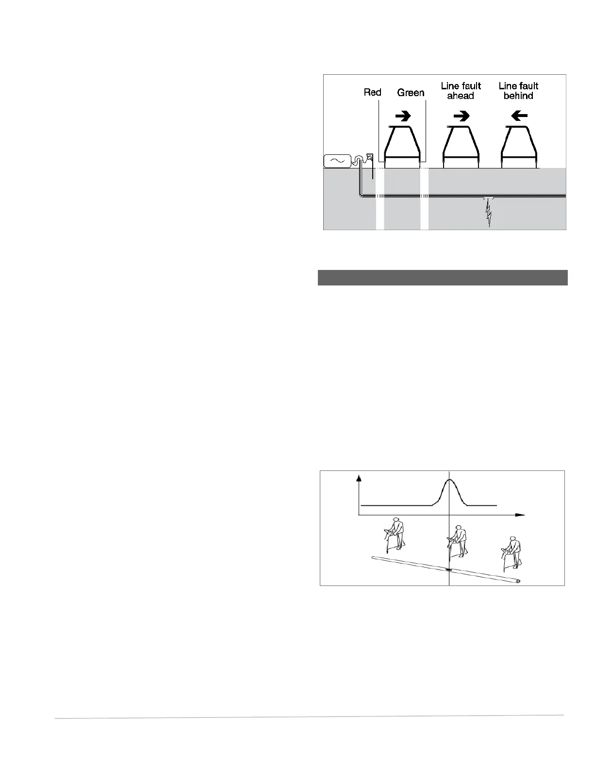
forwards and the red spike towards the
transmitter connection point.
7. The dBuV reading and direction arrow will be
displayed on the screen. Press the antenna key
once to save and store the reading in the PCMx
internal memory.
8. If no fault is apparent or the A-Frame is too far
away from the fault, the arrows will flicker on and off
and the dBuV readings will be erratic – in this
situation move further along the pipeline until the
fault find arrow locks on. When a fault is present,
the Fault Find, (FF) arrows will display the fault
direction and the dBuV readings will be stable. The
dBuV reading will increase as the A-Frame is
positioned closer to the fault.
9. Follow the pipeline pushing the A-Frame spikes into
the ground at regular intervals and checking for
FF arrows.
10. Move in the direction of the arrows. Find the point
at which the arrows change direction. If the A-frame
has been positioned directly above the pipe, the
fault location will be directly below the middle point
of the A-Frame.
11. If the measurements have been taken to the side of
the pipe line, rotate the A-Frame 90° so that the
green spike points towards the pipeline. Move back
and forth across the pipeline to locate the fault in
this direction, the intersection point will be directly
over the fault.
There are two fault find modes on the PCMx locator,
which can be used with the A-Frame:
ACVG
8KFF
On the PCMx locator ACVG fault find uses ELCD and
LFCD outputs from the PCM transmitter. 8KFF is used
when using a Radiodetection transmitter such as the
RD4000 T3, RD4000T10 or the RD7K/8K Tx-5 and Tx-
10.
Note: With the Accessory A Frame plugged in, it is not
possible to take PCMx 4Hz Current readings
unless in simultaneous mode.
Fig. 6.2: A-Frame Fault-Finding
6.8 Comparing Fault Severity
To determine the severity of the fault, and compare
different faults on the pipeline to decide repair priorities,
take the dBuV readings with the A-Frame at 90 degrees
to the pipeline.
Place one of the A-Frame’s spikes directly above the
pipeline, and the other away from the pipeline. Start
approximately 1 meter from the fault position, testing at
25cm (or smaller) intervals. Note the highest dBuV
reading, or save it in the PCMx and note log number.
During the survey, you can switch to locating the pipeline
by pressing the function key and selecting the
appropriate locate frequency.
Fig. 6.3: Comparing fault severity