© 2021 Radiodetection Ltd 12
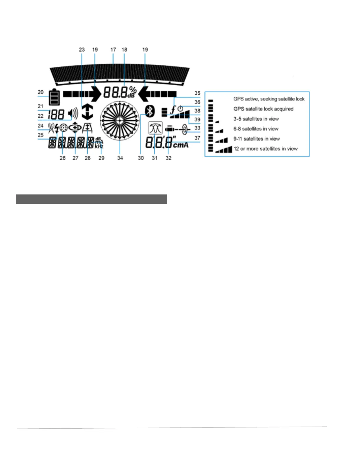
Fig. 4.2: PCMx locator screen icons
4.3 Locator Screen icons
Signal strength bar graph with peak marker.
17. Signal strength bargraph
18. Signal strength readout
19. Null / Proportional Guidance arrows
20. Battery level
21. Sensitivity readout / Log number
22. Volume level
23. Current Direction or Fault Find arrows
24. Radio Mode icon – only on RD8100
25. Power Mode icon
26. Accessory connection indication
27. CD Mode icon
28. A-Frame icon
29. Frequency / current / menu readout
30. Bluetooth status icon: Flashing icon means pairing is
in progress. Solid icon indicates a connection is
active
31. Antenna mode icon: Indicates antenna mode
selection: Peak / Peak+ / Null / Broad Peak /
Guidance
32. Sonde icon: only on RD8100
33. Line icon: Indicates that a line signal source is select
34. Compass: Shows the orientation of the located
cable or sonde relative to the locator.
35. Transmitter communication status - iLOC™
(Tx-1, Tx-5, Tx-10 only)
36. Transmitter standby indicator. (Tx-1, Tx-5, Tx-10
only)
37. Depth readout
38. GPS Status.
39. GPS Signal quality