PCMx Operation Manual
© 2021 Radiodetection Ltd 7
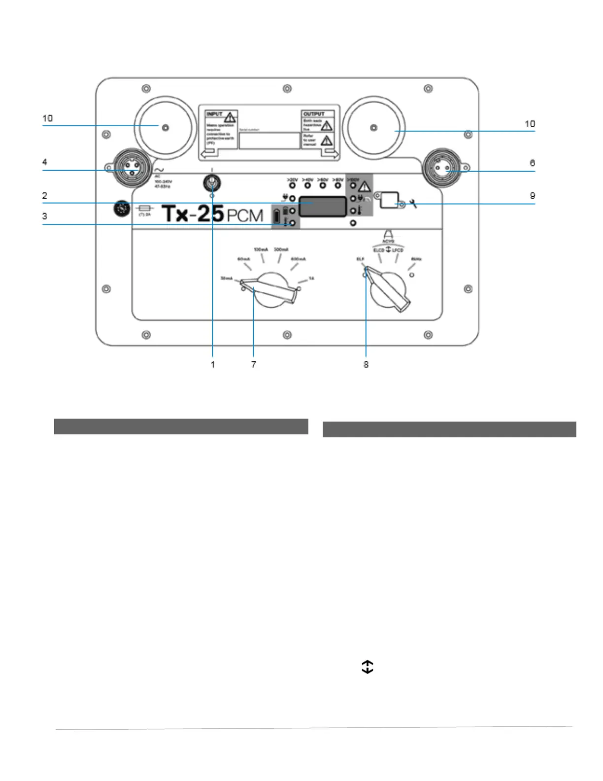
Fig. 3.2: Tx-25 PCM Transmitter
3.2 Transmitter Features
1. On/Off switch.
2. LCD display: Indicates current output, (4Hz or
8kHz) in Amps.
3. LED indicators. Provide critical feedback on
the transmitter’s operation.
4. AC Input socket.
5. DC Input socket (Tx-150 PCM only).
6. Output lead socket.
7. Output Level Selector: Select the output level
in Amps.
8. Frequency Selector: Selects the frequency.
9. Communication Port: For service personnel
only.
10. Heat sink: Vents heat from the transmitter
during operation.
3.3 Transmitter Controls
Frequency Select
The 4Hz current is displayed on the transmitter display.
The frequency selector switch selects the applied
frequencies as follows:
Transmission Lines
ELF Maximum Range
35% 4Hz
65% ELF (128Hz or 98Hz)
Transmission and Distribution Lines
ELCD
Medium Range
35% 4Hz
30% 8Hz (Current Direction)
35% ELF (128 Hz or 98Hz)