PCMx Operation Manual
© 2021 Radiodetection Ltd 35
There was a coated pipeline, which had three defects of
equal electrical resistance, one near the beginning, the
next in the middle and one at the end. If the current loss
graph is prepared using mA on the vertical scale the
second and third faults would be shown as progressively
smaller steps in the graph. This is due to Ohms law, and
the loss of current at the previous fault. See Fig. 8.4.
Fig. 8.4: mA fault graph
Using dBmA as the vertical scale would result in equal
steps in the graph for equal size faults, regardless of how
much current was lost at the first fault. See Fig. 8.5.
Fig. 8.5: dBmA fault graph
The graphs show three equal faults and the effects on a
graph showing mA and dBmA.
Note that the graph showing mA (Fig 8.4) at first glance
suggests that the faults are of diminishing magnitude. The
graph showing dBmA (Fig 8.5) clearly shows the
magnitude of the faults are equal. Therefore, dBmA shows
the ratio of the faults, whereas mA alone may give rise to
misinterpretation of data due to the high current loss near
the transmitter and lower losses further away.
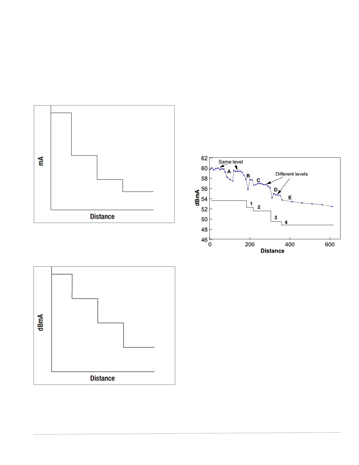
In figure 8.6, the line marked ‘A’ to ‘E’ is the data
collected, whilst the line ‘1’ to ‘4’ is the interpreted data.
Note that at position ‘A’ the current falls and then returns to
almost its original level. This is probably due to field
distortion of the locate signal possibly caused by another
utility line above the pipeline and should be ignored or
further investigation undertaken.
Fig. 8.6: Collected data and interpreted results
Steps ‘B’ to ‘E’ show definite steps (with some field
distortion at the point of fault) and loss of signal. Note
the recovered reading is less than the signal before the
trouble.
Further investigations using the PCMx A-Frame
should now be undertaken so as to pinpoint the exact
position of the faults.