Raisecom
ISCOM2600 (B) Series Product Description
Raisecom Proprietary and Confidential
Copyright © Raisecom Technology Co., Ltd.
Service interfaces (1–12) LEDs
Service downlink interfaces (1–8)
Service uplink interfaces (9–12)
SNMP interface, Console interface, and USB
interface
USB, MST, STK, SNMP, SYS, and PWR LEDs
Figure 2-16 shows the rear panel of the ISCOM2600-12G-DC.
Figure 2-16 Rear panel of the ISCOM2600-12G-DC
2.1.5 ISCOM2600-28X-24F
ISCOM2600-28X-24F-AC/D
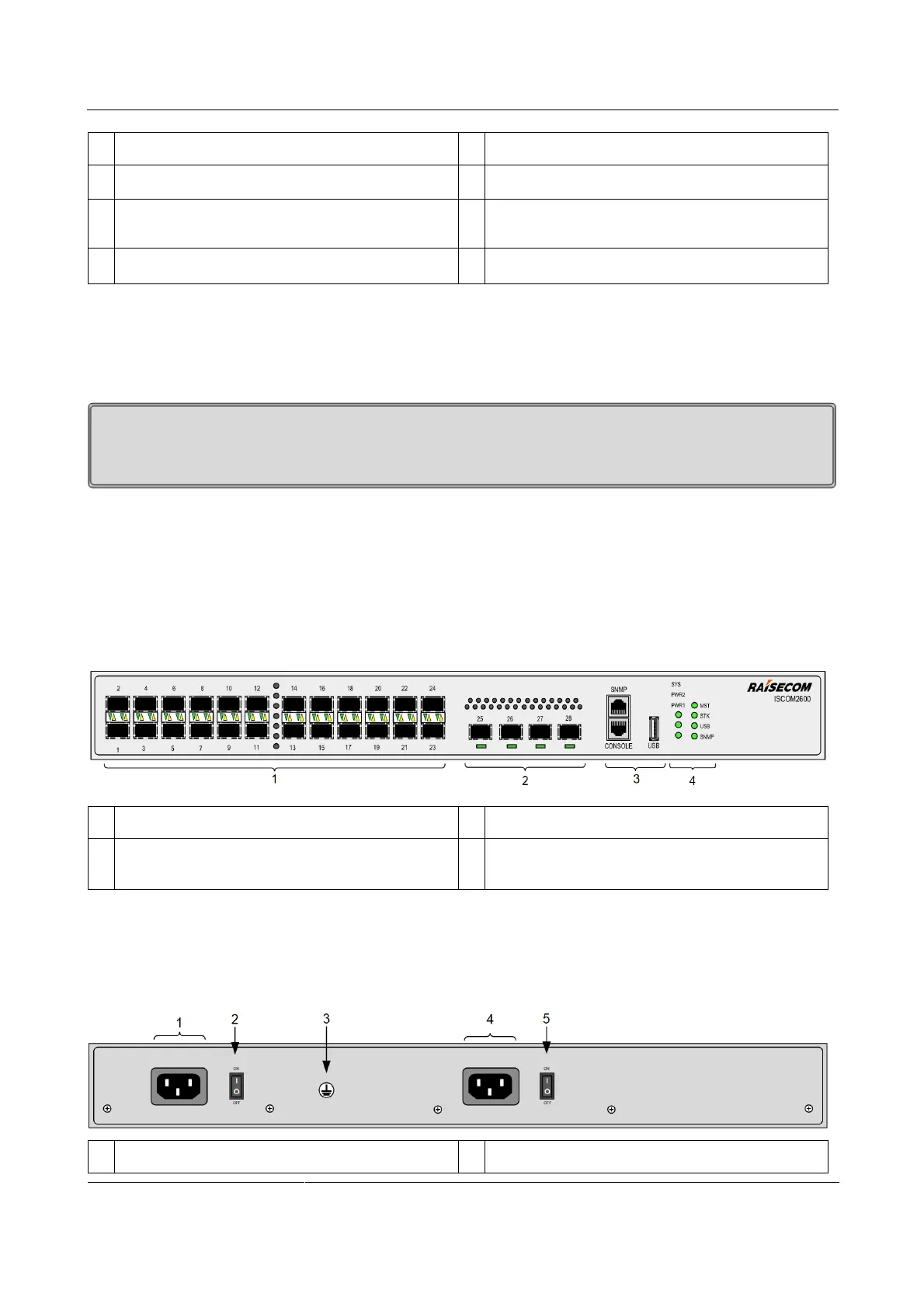
Figure 2-17 shows the front panel of the ISCOM2600-28X-24F-AC/D.
Figure 2-17 Front panel of the ISCOM2600-28X-24F-AC/D
Service downlink interfaces (1–24) and LEDs
Service uplink interfaces (25–28) and LEDs
SNMP interface, Console interface, and USB
interface
SYS, PWR1, PWR2, MST, STK, USB, and
SNMP LEDs
Figure 2-18 shows the rear panel of the ISCOM2600-28X-24F-AC/D.
Figure 2-18 Rear panel of the ISCOM2600-28X-24F-AC/D
Switch for power interface 1
 Loading...


