Raisecom
ISCOM2600 (B) Series Product Description
Raisecom Proprietary and Confidential
Copyright © Raisecom Technology Co., Ltd.
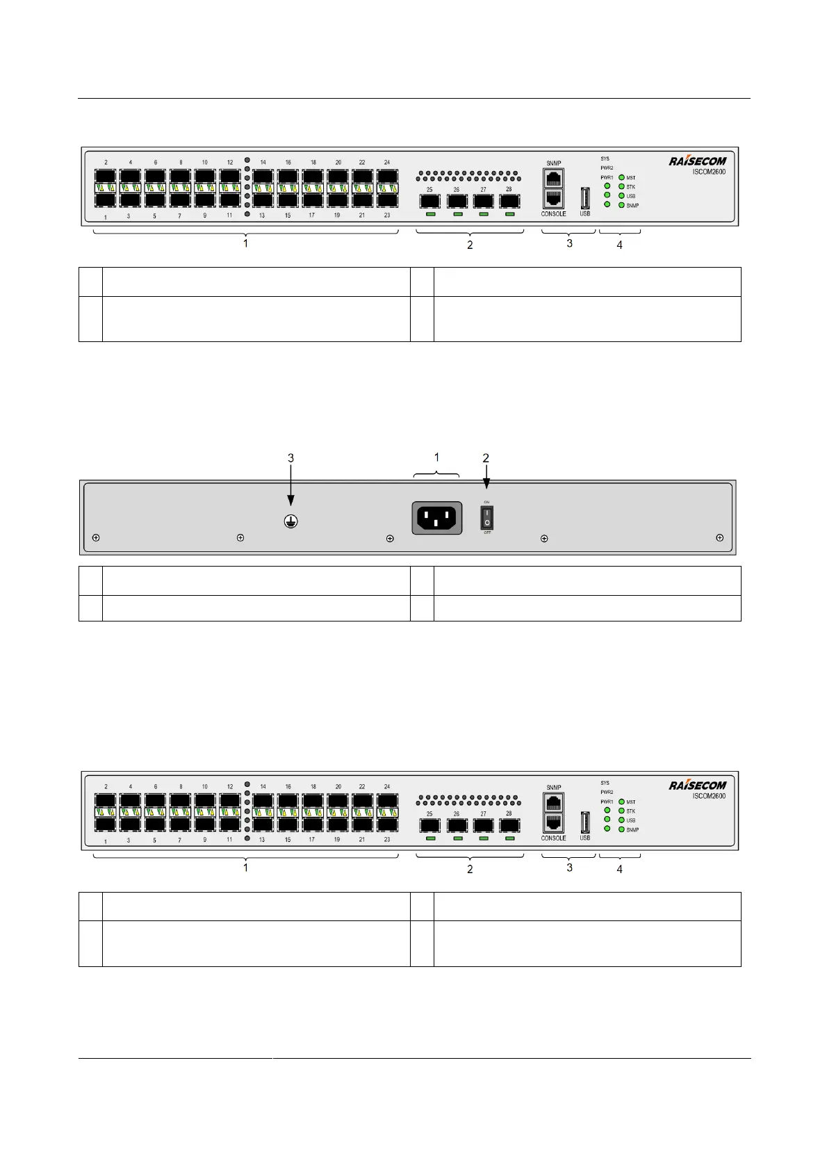
Figure 2-21 Front panel of the ISCOM2600-28X-24F-AC/S
Service downlink interfaces (1–24) and LEDs
Service uplink interfaces (25–28) and LEDs
SNMP interface, Console interface, and USB
interface
SYS, PWR1, PWR2, MST, STK, USB, and
SNMP LEDs
Figure 2-22 shows the rear panel of the ISCOM2600-28X-24F-AC/S.
Figure 2-22 Rear panel of the ISCOM2600-28X-24F-AC/S
Switch for the power interface
ISCOM2600-28X-24F-DC/S
Figure 2-23 shows the front panel of the ISCOM2600-28X-24F-DC/S.
Figure 2-23 Front panel of the ISCOM2600-28X-24F-DC/S
Service downlink interfaces (1–24) and LEDs
Service uplink interfaces (25–28) and LEDs
SNMP interface, Console interface, and USB
interface
SYS, PWR1, PWR2, MST, STK, USB, and
SNMP LEDs
Figure 2-24 shows the rear panel of the ISCOM2600-28X-24F-DC/S.
 Loading...


