Raisecom
ISCOM2600 (B) Series Product Description
Raisecom Proprietary and Confidential
Copyright © Raisecom Technology Co., Ltd.
USB interface working LED
Green: USB deployment is successful. The USB interface is
connected properly.
Fast blinking: the USB interface is transmitting data.
Slow blinking: USB deployment fails.
Off: the USB interface is disconnected, which is the default
status.
ISF master/slave LED
Green: the device is the master in the ISF.
Off: the device is the slave in the ISF, or it is not in an ISF.
ISF status LED
Green: the device is in the ISF mode.
Off: the device is not in the ISF mode.
PoE status LED
Green: the service downlink interface (1–24) LED is in the
PoE status.
Off: the service downlink interface (1–24) LED is in the
working status.
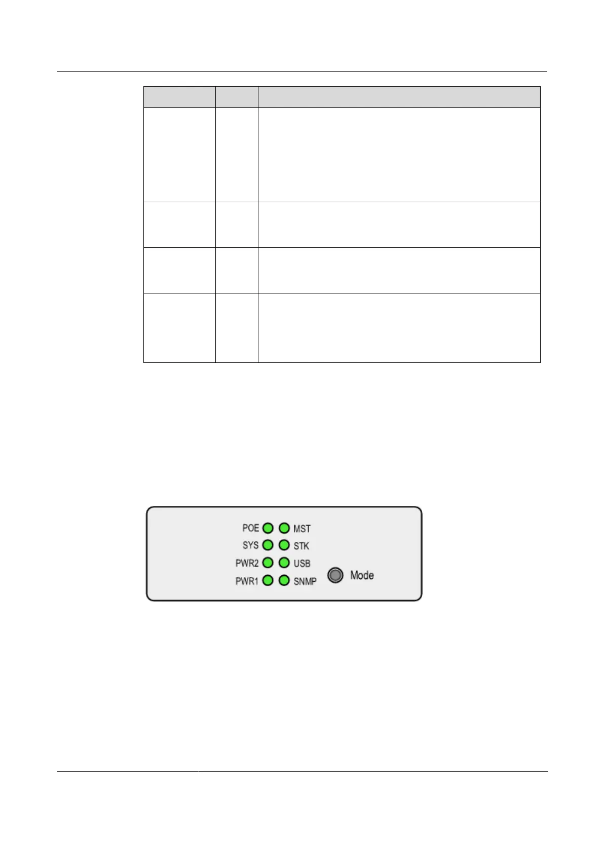
2.4 Button
There is a button on the front panel of the ISCOM2600-28X-PWR and ISCOM2600-28X-
PWH, which is used to switch the LED displaying mode, as shown in Figure 2-35.
Figure 2-35 Mode button on the panel
Table 2-9 describes the Mode button.
 Loading...


