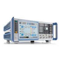
Instrument Control
R&S
®
SMW200A
101Getting Started 1412.9220.02 ─ 21
1 = Status indicator
2 = Functional block
3a / 3b = Control signal block
4 = Signal line (digital)
5a / 5b = Graphics indicator
6 = Signal line (analog)
7a / 7b / 7c / 7d / 7e = Connector icons (RF, analog, digital)
8 = Stream indicator
9a / 9b = Stream status indicator (On/Off)
10a / 10b = Stream indicator (Single, Add)
Starting from left up to the "Stream Mapper", you can see the functional blocks
provided in the baseband domain. After the stream mapper, the analog section
contains the digital to analog conversion and modulation to RF.
Legend Item Description
1 Status indicator Indicates whether the signal is running or waiting for a
trigger.
2 Functional block Represents a basic task in signal generation.
The push button provides access to any number of asso-
ciated actions to accomplish the task.
The On/Off (checkbox) and the block label quickly acti-
vates the basic task.
Understanding the Display Information

 Loading...