Instrument Control
R&S
®
SMW200A
99Getting Started 1412.9220.02 ─ 21
Throughout the manual, the term "select" refers to any of the described methods,
i.e. using a finger on the touchscreen, a mouse pointer in the display, or a key on
the instrument or on a keyboard.
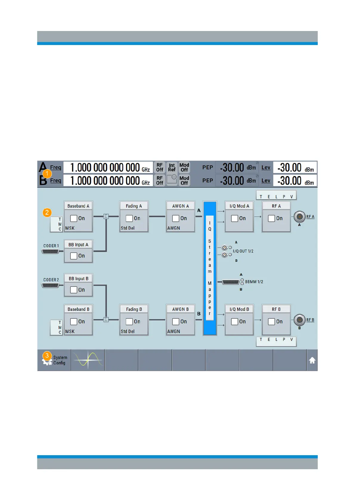
8.3 Understanding the Display Information
The block diagram of the R&S SMW displays all main settings and generator
states, divided into three main operation areas.
Figure 8-1: Block diagram
1 = Status bar
2 = Block diagram
3 = Taskbar/softkey bar
Understanding the Display Information

 Loading...
