Trying Out the Instrument
R&S
®
SMW200A
61Getting Started 1412.9220.02 ─ 21
USER 1
I OUT
(Rear Panel)
Marker 1
Signal
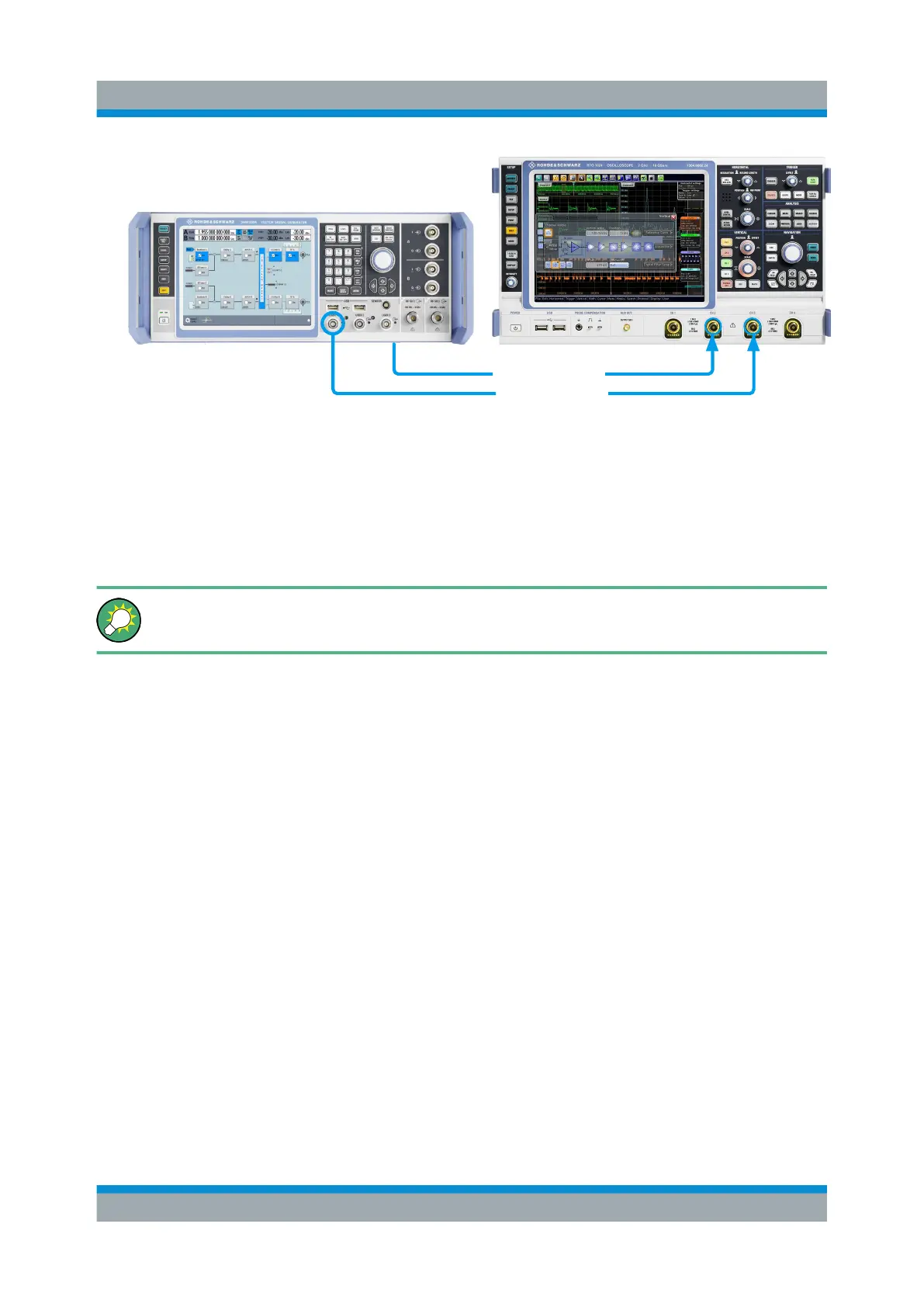
Figure 6-7: Simplified representation of a test setup for signal monitoring**
** = The figure depicts the cabling as a general principle
4. Use a suitable cable to connect the I OUT connector of the R&S SMW to the
monitoring instrument.
To learn more about this topic, refer to chapter "Regular Marker Output Sig-
nals" in the user manual.
6.5 Routing the Signal through the Instrument and
Defining the Output Connectors
This section emphasizes on the signal routing capabilities in the default state of
the instrument (standard system configuration mode). The R&S SMW provides
the "I/Q Stream Mapper" function to route and distribute each of the generated
I/Q signals (streams) to any of the available output connectors.
In the provided example, you use the R&S SMW to generate two baseband sig-
nals, apply a baseband frequency shift, weight them and add them. You then
route the generated stream and define the output connector. The initial situation is
the configuration described in Chapter 6.3, "Triggering the Instrument with an
External Signal", on page 53.
The minimum requirement for the instrument in this example is an R&S SMW
equipped with the options 2xR&S SMW-B10, R&S SMW-B13T, and 2xR&S SMW-
B103.
Routing the Signal through the Instrument and Defining the Output Connectors

 Loading...
