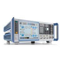
Instrument Tour
R&S
®
SMW200A
37Getting Started 1412.9220.02 ─ 21
SENSOR
Connector for R&S NRP sensors.
A power sensor is connected to the R&S SMW by inserting the male connector.
To disconnect, pull the connector by its sleeve. You cannot disconnect the sensor
simply by pulling at the cable or the rear part of the connector.
The R&S SMW supports the use of R&S NRP power sensors in various ways
including the use as a power viewer.
USER x
Multipurpose connectors. The input/output signal has to be defined.
The Table 5-6 lists the signals assigned to the USER x connectors in the default
instrument state.
Table 5-6: Default configuration of the USER x connectors
USER connector Direction Default assigned signal
1 Output Baseband A Marker 1
2 Output Baseband A Marker 2
3 Input Global Trigger 1
A dedicated LED indicates the connector status:
●
Green: an input connector
●
Yellow: an output connector
●
No light: the connector is not active
See also chapter "Local and Global Connector Settings" in the user manual.
RF A/RF B
Outputs for RF signal of path A and path B.
NOTICE! Maximum input levels. Do not overload the RF output. The maximum
permissible back-feed is specified in the data sheet.
The connector type depends on the installed frequency option, see Table 5-7.
Table 5-7: Overview of RF connector types depending on the frequency range
Required option Connector type
RF A: R&S SMW-B103/-B106
RF B: R&S SMW-B203/-B206
N female
RF A: R&S SMW-B112
RF B: R&S SMW-B212
Test port adapter, PC 3.5 mm female
Front Panel Tour

 Loading...