System Overview
R&S
®
SMW200A
85Getting Started 1412.9220.02 ─ 21
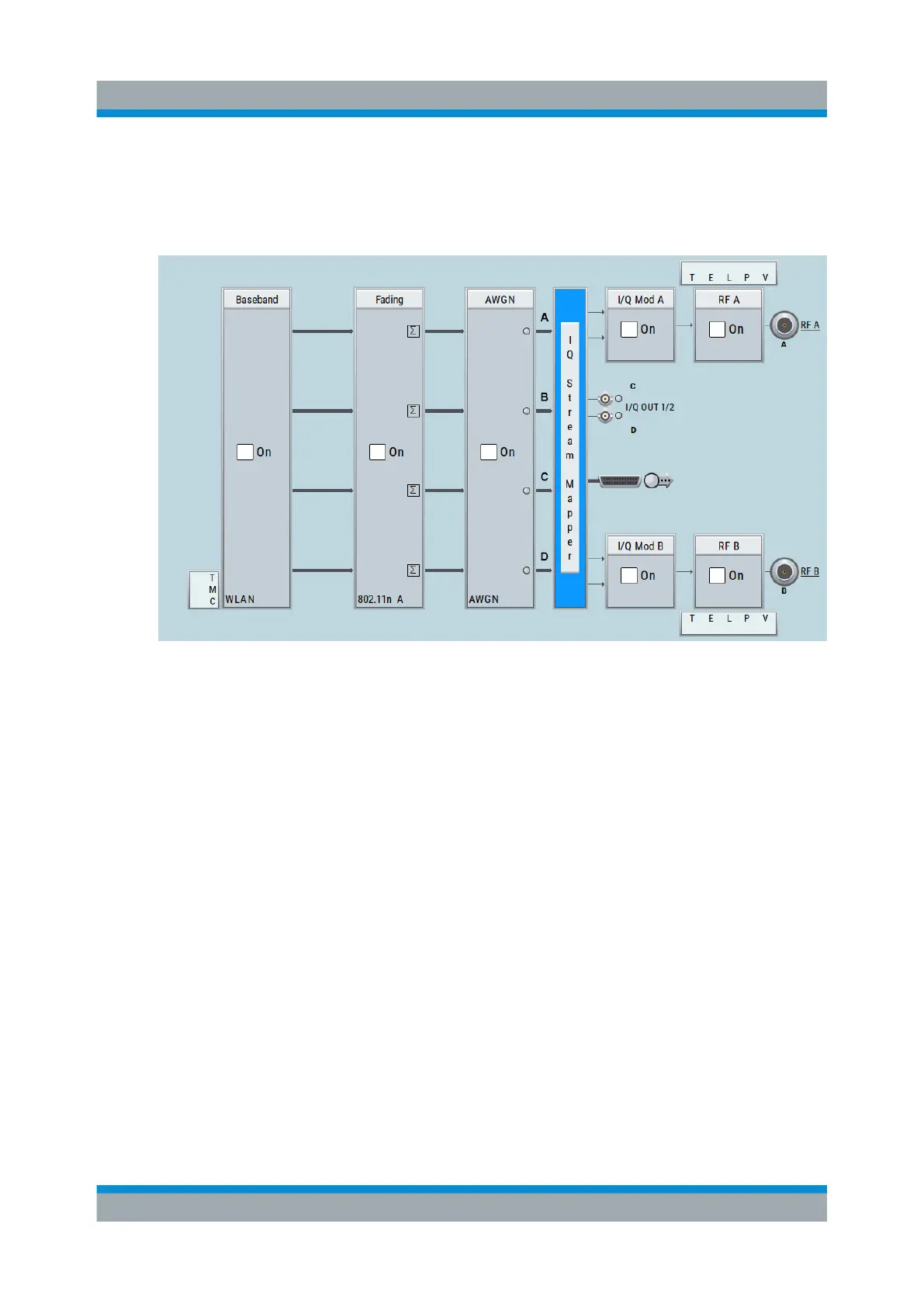
– The block diagram depicting a 4x4 MIMO scenario with coupled baseband
sources is a more abstract representation. Each stage of the signal gener-
ation is still represented by a functional block but the signal routing is dis-
played in a conceptional manner.
Figure 7-2: Block diagram of a fully equipped two path instrument (4x4 MIMO con-
figuration)
For more examples, see also Chapter 7.2, "Applications Examples of the
R&S SMW", on page 90.
The cross-reference between the installed options and the displayed set-
tings
The Table 7-1 is an excerpt of the available options and lists only the options
required to display a functional block in the block diagram. The information
assumes R&S SMW equipped with standard baseband generator R&S SMW-B10
and R&S SMW-B13T.
For exact information on the available options, and on the minimum requirements
and the interdependencies between the provided options, refer to the R&S SMW
data sheet.
Brief Introduction to the Instrument's Concept

 Loading...
