en-67
ADJUSTMENTS 7
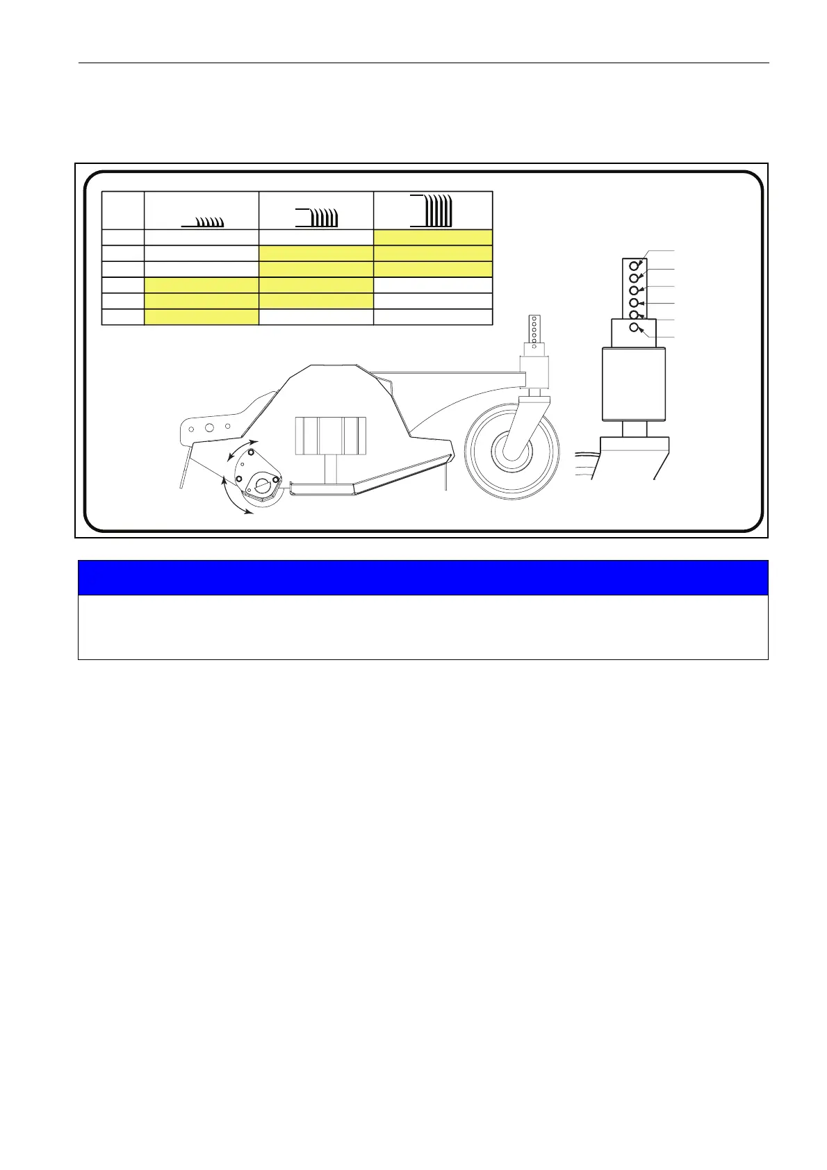
Front castor wheel setup
1. Start the engine and raise the cutting units into the transport position, then engage deck locks. Turn off engine
and remove the ignition key.
2. Remove the quick release pin from the castor wheel stem, refer to the height of cut decal below to determine
the required height of cut depending upon which position the rear roller is located.
3. Install quick release pin into the new hole position for the castor wheel.
4. Repeat instructions two to three on the second castor wheel.
5. Repeat instructions two to four on the remaining cutting units.
6. Once the height of cut has been set, start the engine and lower the cutting units to the ground, turn off the
engine and remove key.
7. Visually inspect the cutting units before use to ensure that the front stone impact protection device is parallel
to the ground before use.
NOTICE
All height of cut measurements shown in the manual are approximate and intended for guidance only.
The height of cut will vary as the flails wear through their life.
It is our recommendation that a test cut is performed before cutting any designated areas.
1
2
3
4
5
6
C
B
A
Highlighted values are recommended settings for optimum performance.
A
B
C
HOLE
1
2
3
4
5
6
46
42
38
34
30
-
65
61
57
53
49
45
80
76
72
68
64
-
683564