UltraVent - Installation done correctly
Ultravent
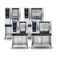
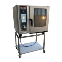
The Ultravent (UV) is a hood which only condensates steam from coming from the unit (1). To lter smoke
particles a UV Plus (2) with an integrated particle lter on top of the hood must be used.
Note: Smell is not eliminated at all.
The UV needs a separate single phase power supply and is controlled by bus system.
The UV is mechanically connected to the unit top door hinge via a separate bolt (3) 60.72.892, which is replac-
ing the rear 8mm screw of the top door hinge. From inside the UV a washer and nut connects to this bolt.
In case this washer and nut are not connected the UV will leak water.
The UltraVent will be started by the BUS signal. (CombiDuo: The UltraVent is connected to the BUS system of
both units.)
The PCB Service part is always equipped with 2 Minit BUS connections
and 2 RJ45 BUS connections.
In case the power supply to the Ultravent or the BUS connection is
faulty, Service 35 (SCC_WE) or E35 (CM_P) will be indicated.
If the UltraVent is nally disconnected, it must be deactivated in “Basic
Settings”.
As soon as the BUS sends the signal „unit is running“ the UltraVent is
running on low speed. When the cabinet door is opened, it will switch to
high speed. Aer ending of cooking program the UltraVent will switch
o, lag time is adjustable.
A UltraVent for CombiDuo and UltraVent Plus has 2 fan motors (ref. to cir-
cuit diagram below).
Oberve the bus connection to the le - right pair for upper and lower unit.
UltraVent Plus
The UV Plus is equipped with 2 lters. The state of the lter is
monitored by dierential pressure switches and positioning switches and indi-
cated by 1 LED each.
Filter 1 (pre lter, 60.72.429 (5ea)) is located directly behind the front grease l-
ters. In order to extend the life of the main lter (2) 60.72.428 the pre lter should
be changed when the middle LED (LED1) is activ.
Filter 2 (main lter) is located on top of the UltraVent. This lter should be changed when the right LED (LED2)
is active.
Should any of the positioning switches remain open (lter not inserted) the le LED 3 „ERROR“ will show red.
Structure of Serial number from 09-2011:
ET1UA11095000126
ET2PA11095000133
Energy, Duo unit size model Version Year Month Serial number
E = Electric
T1 - 61 / 101
T2 - 62 / 102
T3 - 60
C3- 60 with U /
UV combined
I3 - Integration kit
U = UV
P = UVPlus
D = Extrac-
tion hood
B = Baking
A- Basic
Version
11 09 5000126
G = Gas
D = Combi Duo only
electric
F1 = 201
F2 = 202
Bottom unit Top unit
V07 en, Basic_Installation_Accessories - 34 -
The next 2 pages apply to the UV and UVP sold since 2017, the UV with the Door lock and pin solenoid
covered seperately in it install manual and operating instructions. This hood is being phased out once sold out.
US/Canada 12/2018