4
Manual No. 016-5034-004 29
Wheel Angle Sensor Installation
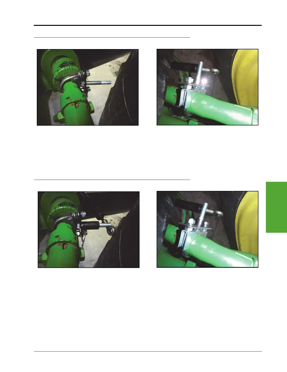
FIGURE 8. Rod Mounting Bracket Installed
9. Install the rod mounting bracket and M10 bolt on the muffler clamp using two 0.325” ID x 0.505” OD x
0.040” thick washers (P/N 313-2301-005) and two 5/16” nylon insert lock nuts (P/N 312-4000-059).
Note: Do not tighten the nuts to allow for adjustment later in the procedure.
Note: The M10 bolt should be pointing toward the rear of the machine.
FIGURE 9. Spacers Installed on Rod Mounting Bracket
10. Install one or two spacers (P/N 107-0172-037) on the M10 bolt, depending on the machine’s configuration.
Note: Single steering cylinder models require two spacers. Dual steering cylinder models require one
spacer.
Single Steering Cylinder Models
Dual Steering Cylinder Models
Left
Front
Tire
Left
Front
Tire
Single Steering Cylinder Models
Dual Steering Cylinder Models
 Loading...


