6 Hardware
Whenever you are servicing a machine, turn the machine off and unplug it!
Most of the described procedures are explained in detail on the Rayjet Video DVD. Please consult
the DVD for additional information.
6.1 X- and Y-axis
The axes are the most strained mechanical components in a laser engraver. As we have to make
sure that the precision is high enough to get a perfect engraving result it is important that possible
positioning errors between incremental resolver and engraving head are minimized (engraving
accuracy at 1000dpi=25.4µm, at cutting 1 increment=10µm).
To assure this, we have to service the axes periodically. The most important one is the X-axis, as it
moves approximately 500 times farther than the Y axis (this is true for square jobs and a resolution
of 500 dpi).
Each of the axes contains some wear and tear parts. These are for example:
- Belts (motor belt and main belt)
- X-motor including drive gear
- Ball bearings and reels
which have to be replaced in case of problems.
On every machine the technician has to decide which of the components are outworn.
CAUTION
The service may only be performed by service technichians that have been trained
by Trotec and are familiar with the hazards from lasers
.
6.1.1 Adjusting the Offset (0/0 position)
If the laser after focussing and “moving home” in the Mini Manager is not at the 0/0 position, you
have to adjust the reference switches.
Steps for checking and adjusting the X and the Y offsets:
1. Focus the beam on the surface of the rulers and put some paper tape at the crosspoint.
2. Move the engraving head to 0/0 (Mini Manager > “move home”)
3. Fire the test pulse (~ 10%) until you can see a small spot on the paper tape.
4. The distance between this spot and the rulers should be smaller than 0.5mm.
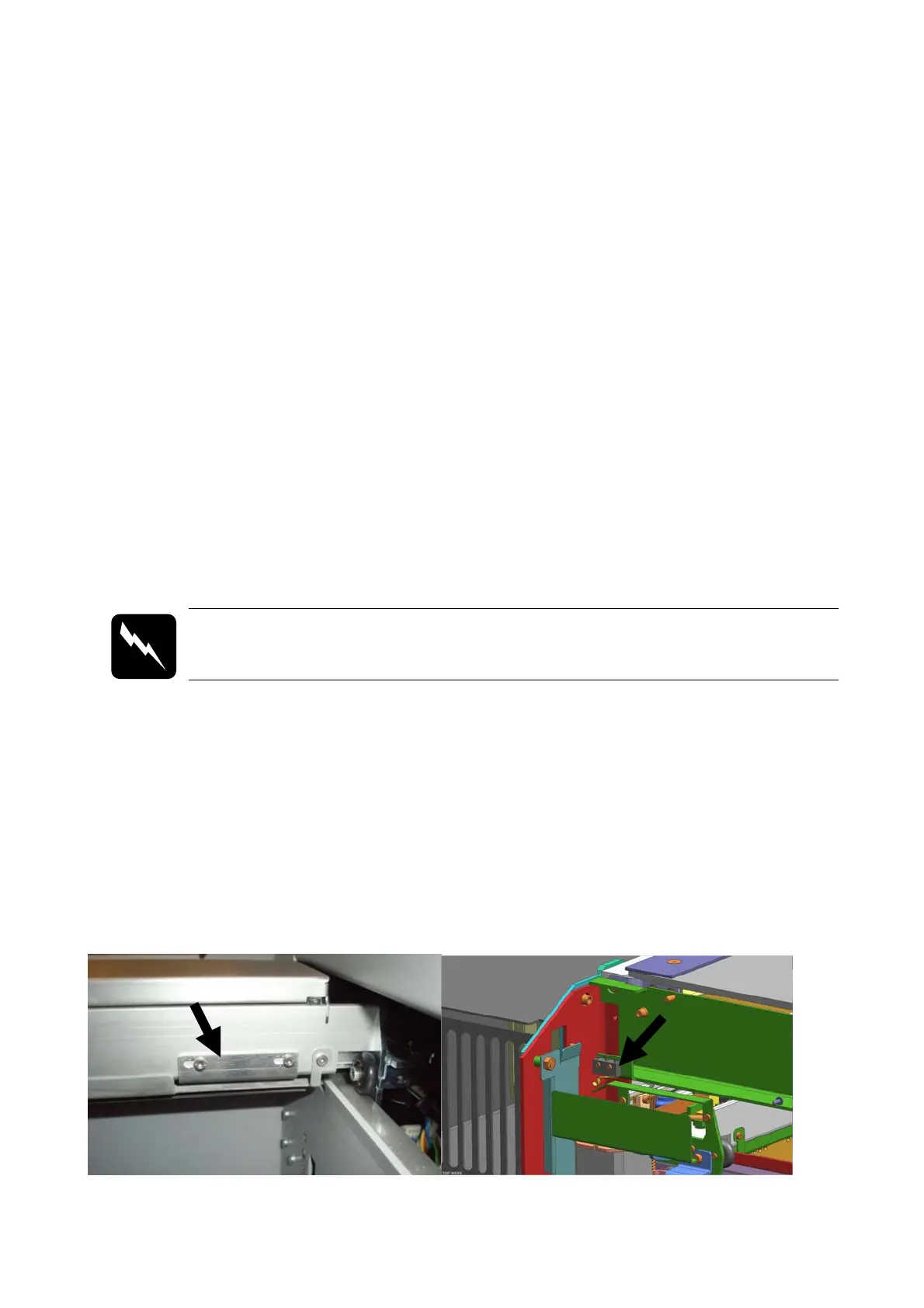
5. If the distance is bigger: you have to align the position of the x-limit switch, placed on the left
backside of x-axis and/or of the y-limit switch placed on the left side of the left y-axis.
x-axis limit switch y-axis limit switch