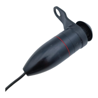
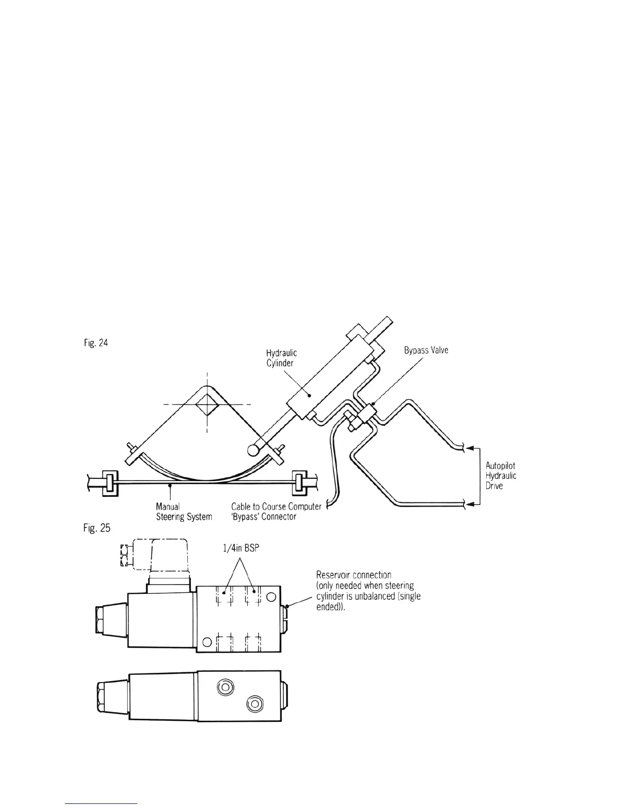
Bypass Valve (Cat. No. Z079) (Fig. 25)
If the autopilot operated hydraulic cylinder is
independent of the manual steering system a
solenoid operated bypass valve should be fitted to
allow the cylinder to backdrive when manual
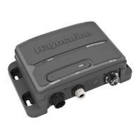
steering. The bypass valve should be connected
to the 'bypass' connector on the Type CR
Interface Unit.
The bypass valve Fig. 24 should be fitted between
the autopilot steering cylinder ports and will
normally be de-energised to allow the cylinder to
backdrive. When the autopilot is engaged, the
valve is energised by the Type CR Interface to
allow the autopilot steering cylinder to drive the
rudder. If the steering cylinder is unbalanced
(single ended) the reservoir connection must be
connected to the reservoir
below the oil level (Fig. 25) to enable excess oil to
be returned and made up to the reservoir.
Note
• The bypass valve voltage must be matched to
the course computer supply voltage i.e. 12V
or 24V.
• If the bypass valve is used on systems with a
reversing gear pump (i.e. without the type CR
Interface Unit) a 5 amp relay should be used
to energise the bypass valve. The relay
should have a 12V coil, taking less than
500ma and be driven by the clutch output on
the course computer connector unit.
21
 Loading...