Both sprockets must be accurately aligned to run
in the same plane and correct alignment must be
carefully checked by means of a straight edge.
The gearbox may be mounted in any convenient
attitude. In addition, the drive sprocket may face
any direction since steering sense can be
corrected when the installation is complete by
reversing the polarity of the drive motor
connection (see section 3.3). Finally, the chain
should be tensioned until it is just tight and
contributes negligible lost motion to the drive
system. Total lost motion between the driven
sprocket attached to the steering system and the
rudder stock should not exceed 2% of total
movement under any circumstances. If lost
motion exceeds this level it must be corrected,
otherwise steering performance will be impaired.
Having completed the drive unit installation, turn
the steering wheel from hardover to hardover and
check that the chain and sprockets driving the
actuator move freely and in alignment.
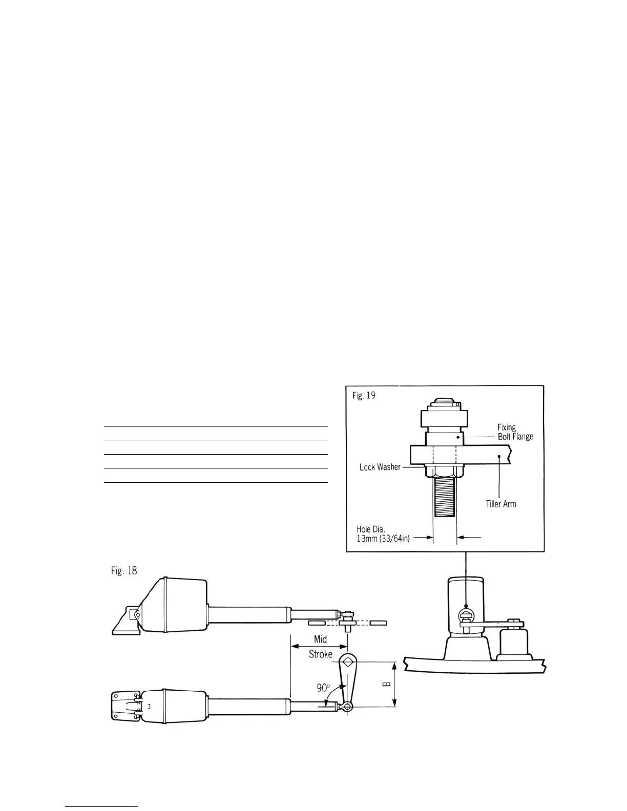
2.2.2 Linear Drive Unit (Fig. 18)
The linear drive unit couples directly to the
rudder stock at the tiller arm radius given below—
Drive Unit Tiller Radius (B)
Type 1 (Z039) 250mm (10in)
Type 2S (Z058,Z059) 250mm (10in)
Type 2L (Z029, Z032) 360mm (14in)
It is preferable to couple the linear drive unit to the
rudder stock via an independent tiller arm
(Edson and Whitlock offer a standard fitting). In
certain cases, however, it may be possible to
couple the pushrod to the same tiller arm or
rudder quadrant employed by the main steering
linkage. It is important to note that the linear drive
system can exert a thrust of over 50OKgs
(1000lbs). If any doubt exists about the strength
of the existing tiller arm or rudder quadrant the
steering gear manufacturer must be consulted.
When siting the linear drive unit, the following
points should be noted:-
• The drive unit mounting bracket may be
attached to any horizontal or vertical surface.
If necessary the drive unit may be mounted
upside down.
• The ball end fitting will allow up to 5 deg.
misalignment between the pushrod and tiller
arm plane of rotation. Accurate angular
alignment is extremely important and under
no circumstances should the above limit be
exceeded.
• The drive unit must be at right angles to the
tiller arm when the tiller is amidships (Fig. 18).
18
 Loading...