XC3000Series Motion Control System of Laser Cutting - User Manual
V1.0 Raytools AG © Copyright 37 |87
www.raytools.ch
(1) Fly Cut Mode:
Circle: select to cut in circular path.
Linear: select to cut in rectangular and polygon-shaped path.
Radar: linear cutting path without smooth arcs. Other cutting modes include Obround and Leadline.
(2) Sort Mode: select different sort modes to use different fly cutting paths.
(3) Starting position: select the start position of the graphic to be processed.
(4) Tolerance: if the horizontal and vertical length of the graphic is smaller than the tolerance, the graphic will be in a line
or an array; if larger, the graphic will be in multiple lines or arrays.
(5) Max Smooth Joint: if the distance between two graphics is less than the max smooth joint length, an arc tangent will
be auto-added to the cutting path to speed up processing and improve efficiency.
(6) Smooth Arc Radius: radius of the arc mentioned in Max Smooth Joint.
(7) Z-axis not Lift Between Fly Groups: select to lift the Z-axis in the travel between two groups in fly cutting.
(8) Laser leads length: laser on in advance for better cutting off the workpiece.
(9) laser lags length: as over-cutting distance, laser off delay is for better cutting off the workpiece.
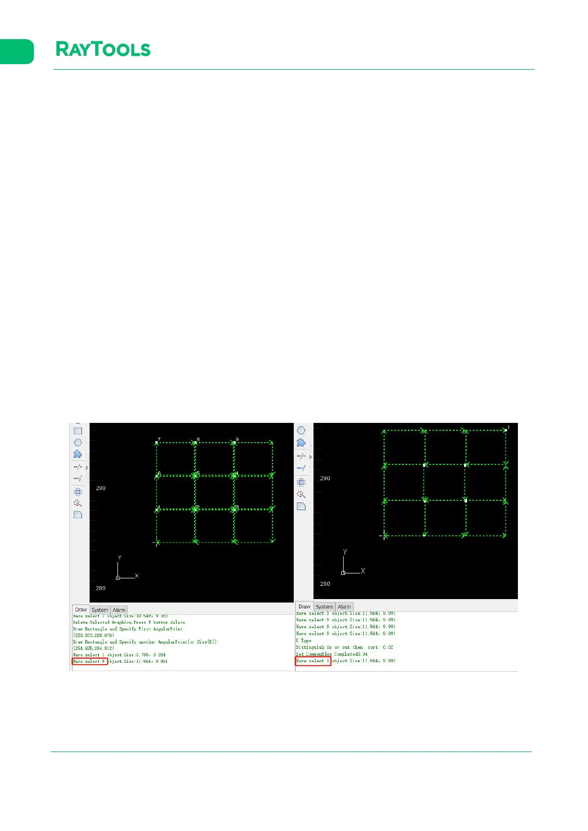
2.1.24 Co-edge
Combine workpieces with common edges to use one edge for cost efficiency and improve processing efficiency.
Select graphics to be co-edged and click on Co-edge button in the Home sub-page. Co-edge parameter setting pops up by
which you can select T-type or common co-edge, and the way to sort. Click on OK to complete. After co-edging, the
graphics will be grouped into one contour to avoid sorting errors. The result of co-edge is shown below:
 Loading...