RC GROUP - 149_ItEn.0102
106
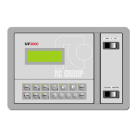
MP2000 AIR CONDITIONERS
Software per condizionatori d'aria a pompa di calore e Roof Top • EPROM CPX....
• Software for heat pump air conditioners and Roof Top
MODE :
Indica il modo di funzionamento dell’umidificatore.
Il display indica con:
START UP - avviamento umidificatore
NORMAL - funzionamento regolare
CYLINDER FULL - cilindro pieno d'acqua
CALIBRAZIONE SONDE
A questo punto, premendo il tasto FRECCIA GIU, il pro-
gramma chiede la "Service Password" per effettuare l'even-
tuale calibrazione delle sonde, come di seguito indicato:
ROOM TEMP.:
Misura temperatura ambiente - aggiustamento ± 9,9°C.
SUPPLY AIR 1:
Misura temperatura aria in uscita dal circuito 1 - aggiusta-
mento ± 9,9°C.
ROOM HUMID.:
Misura umidità relativa - aggiustamento ± 9%rH.
EXT. AIR TEMP.:
Misura temperatura aria esterna - aggiustamento ± 9,9°C.
OUT WATER 1:
Misura temperatura acqua refrigerata in uscita dal circuito
1- aggiustamento ± 9,9°C.
LO PRESSURE 1:
Misura pressione di aspirazione del circuito frigorifero 1 -
aggiustamento ±90kPa .
HI PRESSURE 1:
Misura pressione di condensazione del circuito frigorifero
1 - aggiustamento ±90kPa.
SUPPLY AIR 2:
Misura temperatura aria in uscita dal circuito 2 - aggiusta-
mento ± 9,9°C.
OUT WATER 2:
Misura temperatura acqua refrigerata in uscita dal circuito
2 - aggiustamento ± 9,9°C.
LO PRESSURE 2:
Misura pressione di aspirazione del circuito frigorifero 2 -
aggiustamento ±90kPa.
HI PRESSURE 2:
Misura pressione di condensazione del circuito frigorifero
2 - aggiustamento ±90kPa.
VOLTAGE LINE:
Misura tensione di linea - aggiustamento ±99V.
LINE CURRENT:
Misura corrente di linea - aggiustamento ±9A.
Nel caso non fosse necessaria la calibrazione delle sonde,
premere il tasto HOME per tornare alla maschera principa-
le.
MODE:
Indicates the humidifier’s operating mode.
The display indicates with:
START UP – the humidifier start up
NORMAL – the regular running
CYLINDER FULL – a cylinder full of water
PROBE CALIBRATION
At this point, by pressing the DOWN ARROW key, the
program requests automatically the “service password” to
calibrate probes, if necessary, as indicated below:
ROOM TEMP.:
Room temperature measurement - adjustment
±
9.9
°
C.
SUPPLY AIR 1:
Air outlet temperature measurement in circuit 1 - adjust-
ment
±
9.9
°
C.
ROOM HUMID.:
Relative humidity measurement in the room - adjustment
±
9% r.h.
EXT. AIR TEMP.:
External air temperature measurement - adjustment
±
9.9
°
C.
OUT.WATER 1:
Chilled water outlet temperature measurement in circuit 1
- adjustment
±
9.9
°
C.
LO PRESSURE 1:
Cooling circuit 1 suction pressure measurement - adjust-
ment
±
90kPa.
HI. PRESSURE 1:
Cooling circuit 1 condensing pressure measurement -
adjustment
±
90kPa.
SUPPLY AIR 2:
Air outlet temperature measurement on circuit 2 - adjust-
ment
±
9.9
°
C.
OUT.WATER 2:
Chilled water outlet temperature measurement on circuit 2
- adjustment
±
9.9
°
C.
LO PRESSURE 2:
Cooling circuit 2 suction pressure measurement - adjust-
ment
±
90kPa.
HI. PRESSURE 2:
Cooling circuit 2 condensing pressure measurement -
adjustment
±
90kPa.
VOLTAGE LINE:
Line voltage measurement - adjustment
±
99V.
LINE CURRENT:
Line current measurement - adjustment
±
9 A.
When it is not necessary to calibrate probes, press the
HOME key to return to the main mask.