SERVICE STG
Parameter >
Maintenance >
Functions >
Operation mode >
Diagnostics >
PARAMETER
Time delay open >
Drive >
Entrance system >
Manual control >
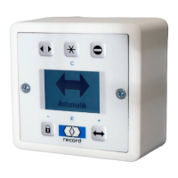
Control panel >
Locking >
12
SERVICE STG
Configure System >
Learning System >
Parameter >
Maintenance >
Functions >
SERVICE STG
Configure System >
Learning System >
Parameter >
Maintenance >
Functions >
Operation Mode >
SERVICE STG
Configure System >
Learning System >
Parameter >
Maintenance >
Functions >
SERVICE STG
Configure System >
Learning System >
Parameter >
Maintenance >
Functions >
Operation Mode >
PARAMETER
Time delay open >
Drive >
Entrance system >
Manual control >
Control panel >
Locking >
\
LOCKING
Locking function 1
Locking type 1
Manual 0
Start delay 0
MANUAL LOCKING
0 disabled
1 enabled
When enabled, a short between
terminals 23 and 24 will prevent
automatic operation. A lock monitor
switch can be used to inhibit opera-
tion until the lock has unlocked.
“Manual Lock” will be shown on the
display control panel and the FPC-
902 Terminal.
When electric locking is enabled,
actuation of the control will cause
the lock relay to immediately close,
followed by the Start Delay, then the
operator begins to open the door.
0 = 1/2 second delay
1 - 40 increases delay in 0.2 second
increments (20 = 4.5 second delay)
\
LOCKING
Locking function 1
Lock type 1
Manual locking 0
Start delay 0
START DELAY
0
SERVICE STG
Configure System >
Learning System >
Parameter >
Maintenance >
Functions >
SERVICE STG
Configure System >
Learning System >
Parameter >
Maintenance >
Functions >
Operation Mode >
SERVICE STG
Configure System >
Learning System >
Parameter >
Maintenance >
Functions >
SERVICE STG
Configure System >
Learning System >
Parameter >
Maintenance >
Functions >
Operation Mode >
PARAMETER
Input / Output >
CAN-BUS >
Miscellaneous >
Manual control >
Control panel >
Locking >
CAN-BUS
FEM1 0
AKI 1 0
SI 1 0
AKA 1 0
SA 1 0
AKI 2 0
Communication to program sensors
through Canbus.
Currently used with FEM Modules,
SERVICE STG
Configure System >
Learning System >
Parameter >
Maintenance >
Functions >
SERVICE STG
Configure System >
Learning System >
Parameter >
Maintenance >
Functions >
Operation Mode >
SERVICE STG
Configure System >
Learning System >
Parameter >
Maintenance >
Functions >
SERVICE STG
Configure System >
Learning System >
Parameter >
Maintenance >
Functions >
Operation Mode >
PARAMETER
Input / Output >
CAN-BUS >
Miscellaneous >
Manual control >
Control panel >
Locking >
INPUT / OUTPUT
STG >
FEM 1 >
INPUT / OUTPUT
STG >
FEM 1 >
STG
AUX 1_IN 1
Ext. Sw IN 2
Ext. Sw IN_F 0
AUX1_IN
0 disabled
1 BEA Bodyguard
If a transom/header mounted
swing-side safety sensor is
used, AUX1_IN (Terminal 8)
should not be disabled. This
input is ignored during the
closing cycle.
SERVICE STG
Configure System >
Learning System >
Parameter >
Maintenance >
Functions >
SERVICE STG
Configure System >
Learning System >
Parameter >
Maintenance >
Functions >
Operation Mode >
SERVICE STG
Configure System >
Learning System >
Parameter >
Maintenance >
Functions >
SERVICE STG
Configure System >
Learning System >
Parameter >
Maintenance >
Functions >
Operation Mode >
PARAMETER
Input / Output >
CAN-BUS >
Miscellaneous >
Manual control >
Control panel >
Locking >
INPUT / OUTPUT
STG >
FEM 1 >
STG
AUX 1_IN 1
Ext. Sw IN 2
Ext. SW 1
EXT. SW_IN
0 Ext. Sw IN
2 Railbeam
If a safety beam has been
installed in the outer end of a
guide rail, it’s N.C. output
should be connected
between terminals 4 & 5, and
this parameter should be set
to “2 Railbeam”.
RIC290 Sensors and RC Swing On-
Door Sensors in North America.
EMERG.
AUX 1_
Sequent
13 CLOSING BUTTON
CLOSING BUTTON is used
to close door with a pulse in
Input AUX1_IN to abort an
active hold-open time.
AUX 1_
Sequent
 Loading...