SERVICE STG
Parameter >
Maintenance >
Functions >
Operation mode >
Diagnostics >
Learning System
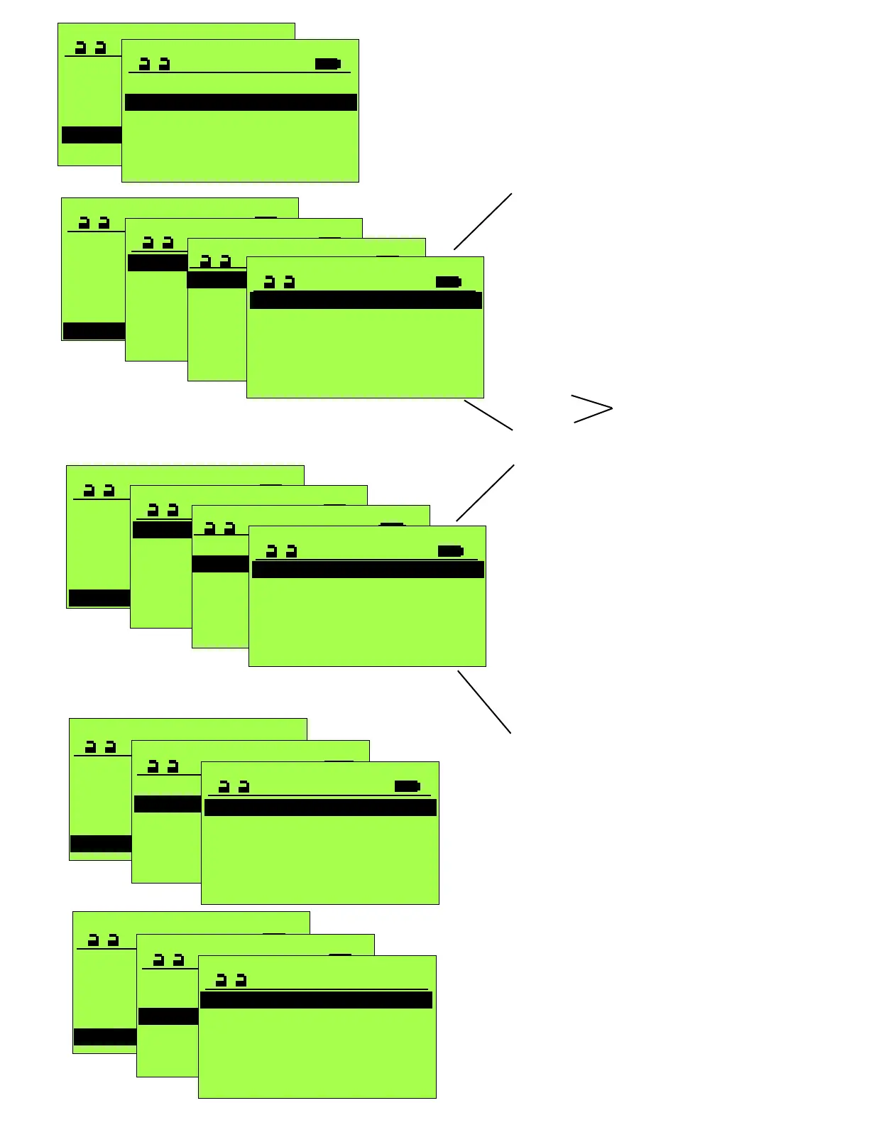
DIAGNOSTICS
Cycles XXXX
Hours XXX
Error history >
Door parameters >
Input >
Displays approx. 100 errors that have occurred
Useful in determining what has been occurring
with the operator and when, prior to servicing.
Delete history will clear the memory of all
previous error codes.
SERVICE STG
Parameter >
Maintenance >
Functions >
Operation mode >
Diagnostics >
Learning System
18
This screen provides a real time status for each
of the control’s inputs via CANBus. A “0” indicates
the input is not actuated, a “1” indicates it is actuated.
AKI = Approach Sensor
AKA = Two-Way traffic 2nd Approach Sensor
SSK = Remote Switch (active when unit is off)
SIS = Door Mounted Approach Sensor
SIO = Door Mounted Swing-side Safety Sensor
RAILBEAM = Guide Rail Safety Beam
BEA Bodyguard = Transom mounted Safety
Protocol >
DIAGNOSTICS
Cycles XXXX
Hours XXX
Error history >
Door parameters >
Input >
Protocol >
CAN-BUS >
Software >
INPUT
STG >
FEM 1 >
SOFTWARE
AKI 0
AKA 0
SSK 0
SIS 0
SIO 0
RAILBEAM 0
CAN-BUS >
Software >
INPUT
STG >
FEM 1 >
STG
AKI 0
AKA 0
SSK 0
SIS 0
SIO 0
AUX1_IN 0
This screen provides a real time status for each
of the control’s inputs that are hardwired. A “0” indicates
the input is not actuated, a “1” indicates it is actuated.
AKI = Approach Sensor
AKA = Two-Way traffic 2nd Approach Sensor
SSK = Remote Switch (active when unit is off)
SIS = Door Mounted Approach Sensor
SIO = Door Mounted Swing-side Safety Sensor
MF_Push Button
AUX1_IN = Auxilliary Input
EMERGENCY STOP
VAK= Lock status
BDEM_1= Mechanical Panel 1 status
BDEM_2= Mechanical Panel 2 status
RESET
SERVICE STGSERVICE STG
Learning System >
Parameter >
Maintenance >
Functions >
Operation Mode >
Diagnostics >
DIAGNOSTICS
Cycles XXXX
Hours XXX
Error history >
Door parameters >
Input >
Protocol >
ERROR HISTORY
Delete history >
25 Slave-connection
39 Overload 24V
88 Diff. parameter
43 Encoder fault
3 Int. Sens. >60s
SERVICE STGSERVICE STG
Learning System >
Parameter >
Maintenance >
Functions >
Operation Mode >
Diagnostics >
DIAGNOSTICS
Cycles XXXX
Hours XXX
Error history >
Door parameters >
Input >
Protocol >
Displays connections and changes made
to the unit and the time frame indication.
2 weeks ago
AUX1_OUT Locked >
AUX1_OUT Test sensors >
Language ENGLISH US >
FPC >
FPC >
AUX1_OUT Closed >
with a time stamp indication; Minutes, days, weeks.
S_AUS
SEA
SFS_IN
Inputs/Outputs of the FEM1
in the Interlock mode
SERVICE STG
Parameter >
Maintenance >
Functions >
Operation mode >
Diagnostics >
Learning System
OPERATION MODE
One-way
Manual
Automatic
Continuously open
OFF (or Locked)
Indicates the current operational mode of the door.
Note this screen does not dynamically update in
response to changes to the control panel.
The Status screen, accessible anytime the terminal
is servicing the unit (STG), will dynamically update
in response to changes to the control panel(s).
 Loading...