• The bus must basically be terminated at both ends
( = terminating resistance 120
Ω)
.
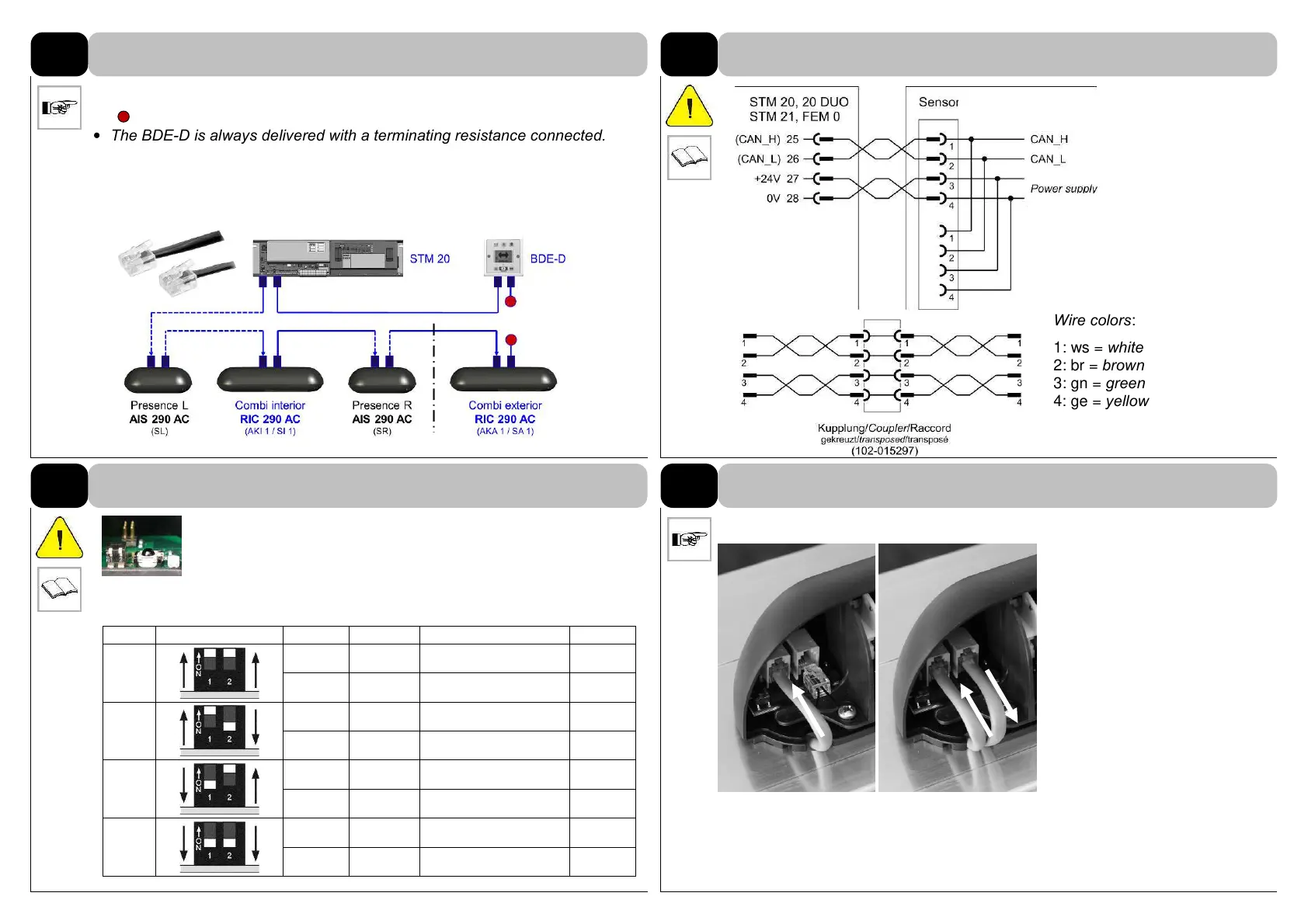
• The BDE-D is always delivered with a terminating resistance connected.
• Only use the cables delivered by record.
102-020808481 cable CAN, 3’3” (1000 mm)
102-020808718 cable CAN, 5’ (1500 mm)
102-020808406 cable CAN, 8’2” (2500 mm)
Wire colors:
1: ws = white
2: br = brown
3: gn = green
4: ge = yellow
15
DIP1: Defines sensor position interior or exterior
DIP2: Defines sensor # 1 or 2
Identification of the sensors, in case several of the same type
are installed. Address the sensors or adjust the DIP switches before being
installed and connected to the CAN bus!
Plug in the connector(s) care-
fully.
If only one CAN-cable is
connected, please plug in the
CAN-termination on the other
connector.
No free socket!
RIC # DIP switch setting Device Function Output signal IR-Code
1
AKI 1
RAD Actuating “inside" 1
SI 1
AIR Safety “inside” 11
2
AKA 1
RAD Actuating "outside" 3
SA 1
AIR Safety "outside" 13
3
WIRING
CAN bus system (figure shows an example)
3.1
Wiring
3.2
DIP switches to address the sensor
3.3
Plug in the connecting cable
Sensor Connections
Left; In Right; Out
Termination
Resistor Plug
Example of sensor cable routing on backside of cover into
header.
Note: See page 15 table for addressing multiple
sensors on each side of unit.