Mosaic fieldbus modules
8540801 • 01/02/2017 • Rev.15 17
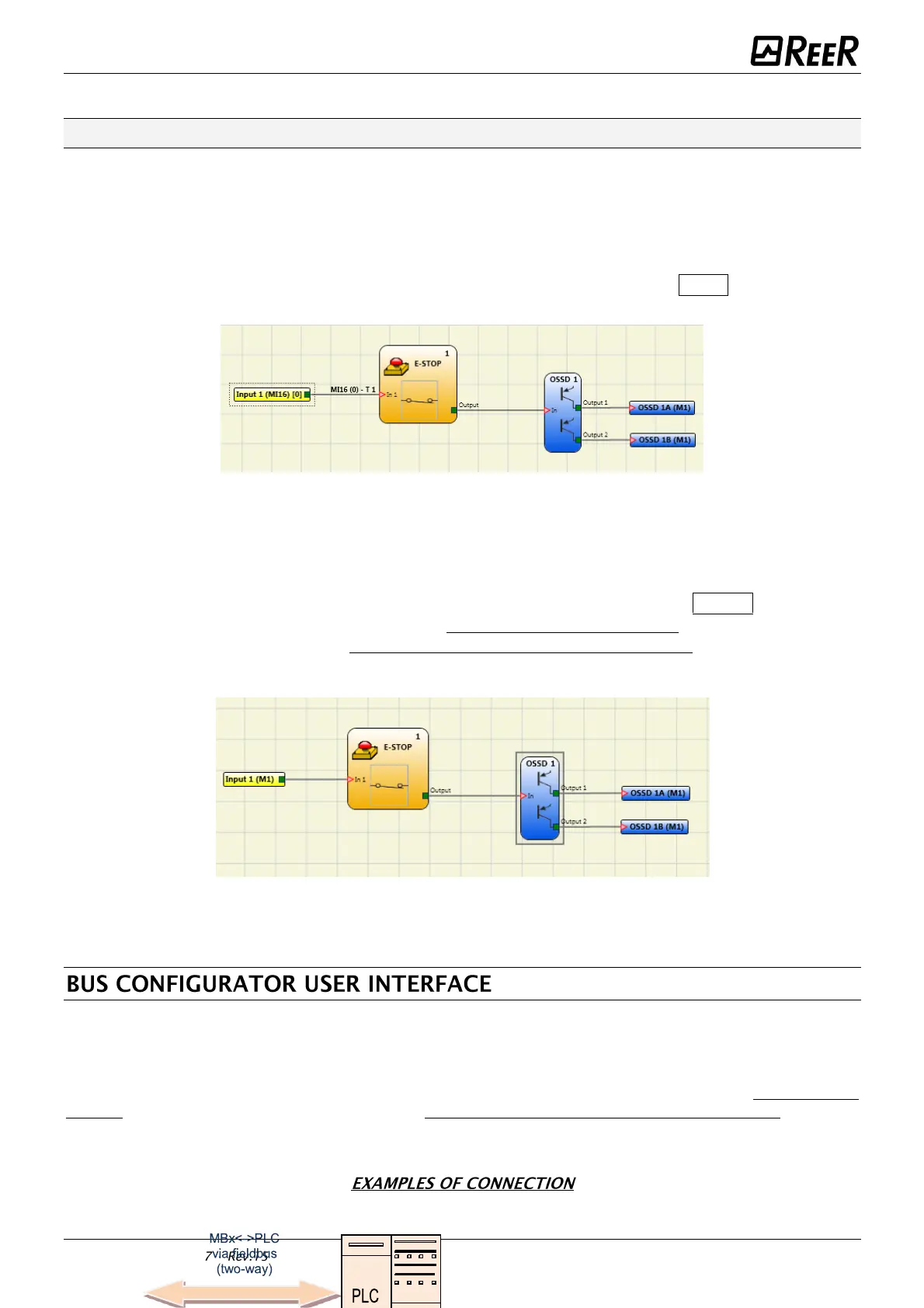
Example 3
The example in Figure 6 is similar to example 1, except in this case Input1 is connected to
module MI16 and is tested with the MI16-T1 test signal.
During wiring, the 24Vdc is connected to input 1 instead of the MI16-T1 test signal.
Input 1 has diagnostic code 10 (OUT_TEST error) and OUT_TEST MI16-T1 has diagnostic code 8
(Connection error).
-
The I/O index and Diagnostic code fields assume the following values: 1 - 20 to indicate the
diagnostics on input 1 of module MI16.
Figure 6
In the example shown in Figure 7 the manual reset function is enabled on OSSD 1.
The pushbutton connected to input 1 is pressed without sending a reset command.
-
The I/O index and Diagnostics code fields assume the following values: 192 - 2
-
to indicate the diagnostics on OSSD 1A/1B (Table 2: 192 = first output).
-
to indicate the diagnostic code (Table 4: 2 = Waiting for OSSD to restart).
Figure 7
The bus module is configured using the USB miniB interface on the front panel and “BUS CONFIGURATOR”
SW installed on the MSDESIGNER CD ROM disk.
This SW can be used for configuration/communication of the MOSAIC system with a PC (using an MBU
module) or to display data transmitted via bus (via connection to the USB port of a bus module).
The diagram below is helpful for understanding possible connections:

 Loading...


