Mosaic fieldbus modules
8540801 • 01/02/2017 • Rev.15 8
Each input and each safety output is associated with a relative diagnostic code.
When the I/O is connected correctly, the diagnostic code is OK and is not exported to the
fieldbus; if there is a problem on the I/O, the system exports 2 bytes to the fieldbus with:
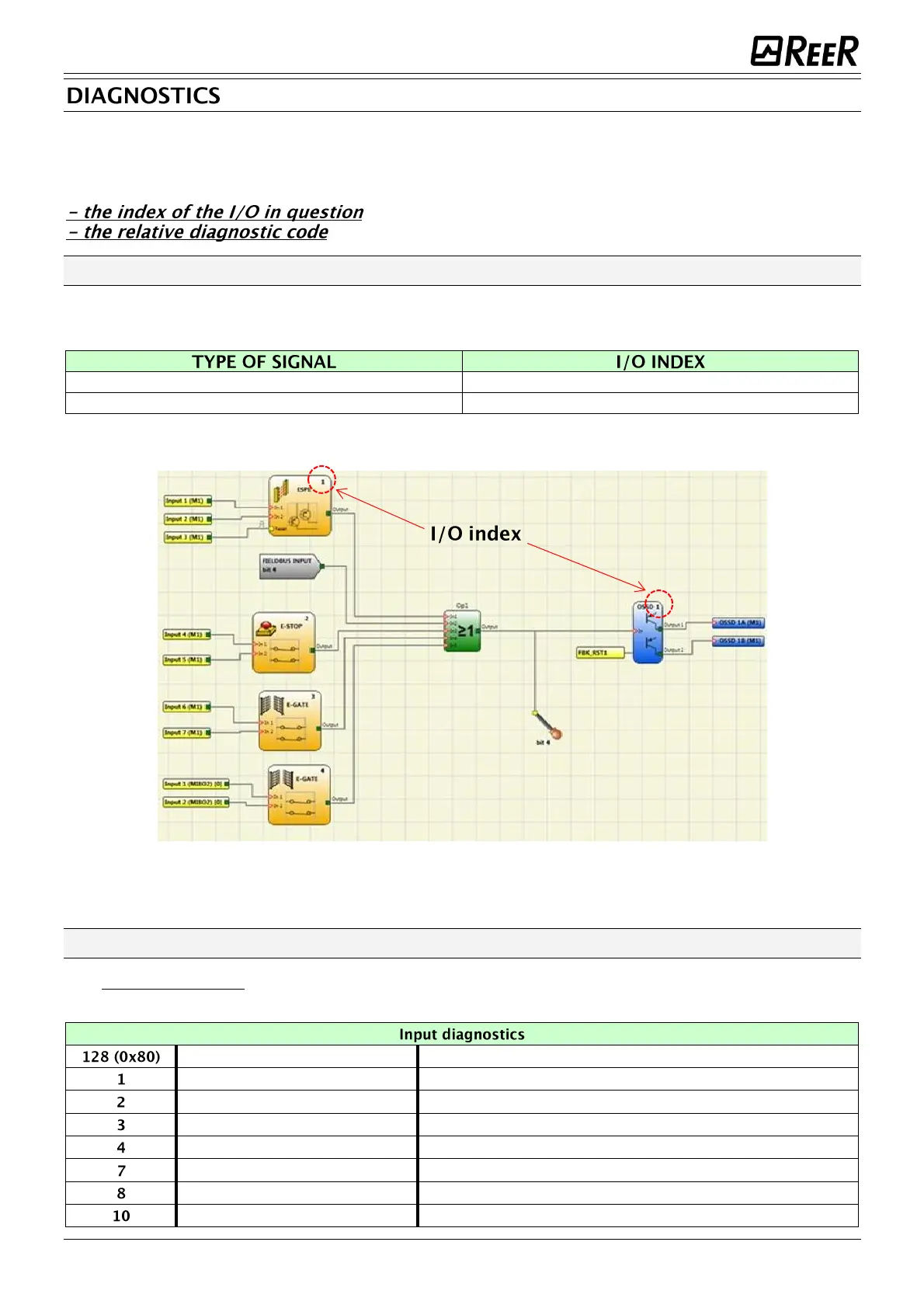
The "I/O index" field
This field indicates the number used to identify the I/O with a diagnostic code other than OK.
Possible values for this field are shown in Table 2.
Table 2
Figure 3- Index of I/O
The "Diagnostic code" field
The "Diagnostic code" field indicates the diagnostics for the I/O. Possible values for this field are
shown in Tables 4, 5 and 6.
Both switches have to go to rest condition
Both switches have to change state simultaneously
Wrong connection on one side of a two-hands switch
Wrong connection on one side of a two-hands switch
The selector should not have more than one input set
The selector should have at least one input set
OUT_TEST diagnostics present on this input

 Loading...


