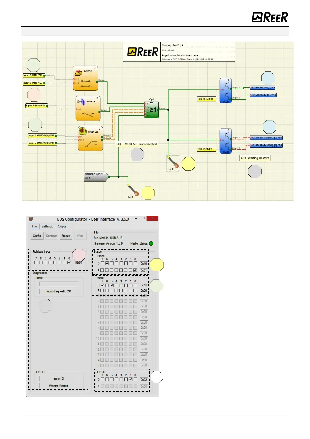
Input 1 E-STOP is connected to screws 6 and 7
on M1. Its status (zero or one) is shown on bit 5
of byte 0 reserved for inputs. The bit 6 is always
set to zero, it is kept busy to signal thea the
E-STOP occupies two screws on M1.
Input 2 ENABLE is connected to screw 8 on M1.
Its status (zero or one) is shown on bit 7 of byte
0 reserved for M1 inputs.
Input 3 MOD-SEL is connected to screws 1 and 2
on MI802 with a diagnostic signalling that the
MOD-SEL is disconnected. Its status is shown on
bits 0 and 1 of byte 1 reserved for MI802
inputs. The diagnostic is shown in the section
reserved for input diagnostics with the index 2
and the relative diagnostic.
The probes on bit 6 and bit 8 are green and the
relative bits on the Probe section are checked.
Probe 8 is shown as bit 0 of the second byte.
OSSD 1 is ON and connected to the second pair
of M1 outputs. Its status is shown on bit 1 of
byte 0 reserved for outputs.
OSSD 2 is OFF with diagnostic indicating wait
for restart and is connected to the second pair
of MI802 outputs. Its status is shown on bit 2 of
byte 0 reserved for outputs. The diagnostic is
shown in the section reserved for OSSD
diagnostics with the index 3 and the relative
diagnostic.
In the Virtual Input section, bit 0 has been
selected so the Fieldbus input on bit 0 is green
in the MSD project.

 Loading...


