EasyManua.ls Logo

Reer Mosaic Series - SIGNALS AND PINOUT; Module MBC

Reer Mosaic Series
22 pages
Print Icon
To Next Page IconTo Next Page
To Previous Page IconTo Previous Page
Loading...
Mosaic fieldbus modules
8540801 • 01/02/2017 • Rev.15 10
OSSD diagnostics ok
Enable Missing
Waiting for restart OSSD
Feedback K1/K2 missing
Waiting for other micro
Redundancy check failed on OSSD
OSSD power supply missing
Exceeded maximum time restart
Feedback K1/K2 external not congruous CAT2
Applicable to MOR4 e MOR4S8 modules configured in CAT2
Waiting for feedback K1/K2
Feedback K1 K2 in Transition
Overload OSSD output
OSSD with Load set to 24V
Table 4
If there are diagnostics for more than one I/O, the and signals
are sent in turn every 500ms.
MEANING
LED
ON
RUN
IN FAIL
EXT FAIL
LED1
LED2
GREEN
GREEN
RED
RED
RED/GREEN
RED/GREEN
Startup - Initial test
ON
ON
ON
ON
ON
ON
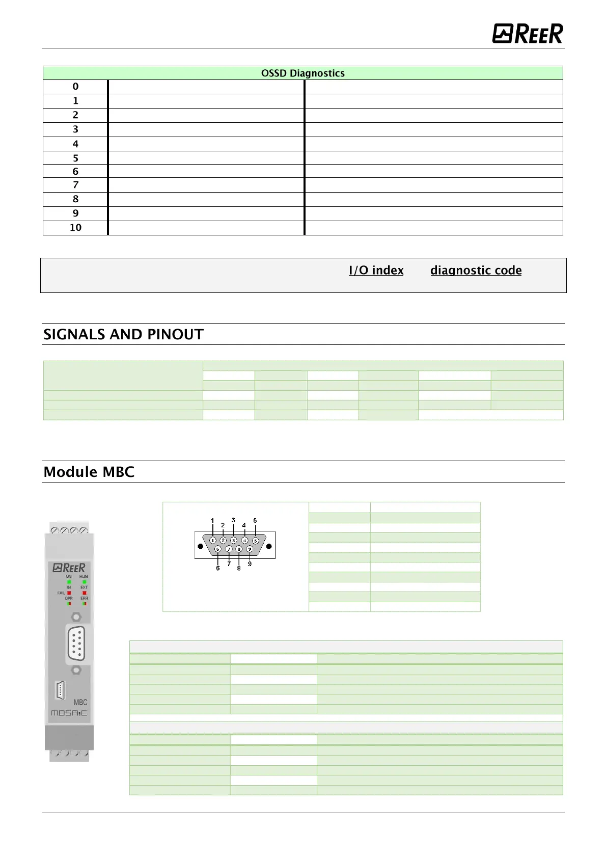
Waiting for configuration from M1
ON
blinking
OFF
OFF
OFF
OFF
Received configuration from M1
ON
ON
OFF
OFF
see the modules tables
Table 1 Initial/ dynamic view.
DB9 male
(front view)
Pin
Signal
1
-
2
CAN_L
3
CAN_GND
4
-
5
CAN_SHIELD
6
-
7
CAN_H
8
-
9
-
Housing
CAN_SHIELD
LED OPR
STATUS
INDICATION
DESCRIPTION
GREEN
OPERATIONAL
OPERATIONAL status
GREEN blinking slow
PRE-OPERATIONAL
PRE-OPERATIONAL status
GREEN 1 flash
STOPPED
STOPPED status
GREEN blinking fast
Autobaud
Baud rate detection
RED
EXCEPTION
EXCEPTION status
LED ERR
STATUS
INDICATION
DESCRIPTION
OFF
-
Normal operation
RED 1 flash
Warning level
A bus error counter has reached the warning level
RED blinking fast
LSS
LSS service operative
RED 2 flashes
Event Control
Detected Node Guarding (NMT master or slave) or Heartbeat (Consumer)
RED
Lack of BUS
BUS not working

Other manuals for Reer Mosaic Series

Related product manuals