12 | Grandview® G800EC Gas Fireplace
owner's information
Proflame II remote control operating instructions
PROFLAME II REMOTE CONTROL OPERATING INSTRUCTIONS
WARNING: THE TRANSMITTER AND RECEIVER ARE RADIO
FREQUENCY DEVICES. PLACING THE RECEIVER IN OR
NEAR METAL MAY SEVERELY REDUCE THE SIGNAL RANGE.
The Profl ame 2 Tr ansmitter provides for controlling the following hearth
appliance functions:
1. Main Burner On/Off
2. Main Burner fl ame modulation (6 levels)
3. Choice of standing or intermittent pilot (CPI/IPI)
4. Thermostat and Smart thermostat functions
5. Accent light modulation (6 levels)**
6. Top Light**
7. Comfort Fan speed modulation (6 levels)**
** This feature is not available on all models.
IMPORTANT:The Profl ame Transmitter 2 is an integrated part of the
Profl ame 2 System, which consists of these elements:
• Profl ame 2 Transmitter, to be used in conjunction with:
• Integrated Fireplaces Control (Profl ame 2 IFC)
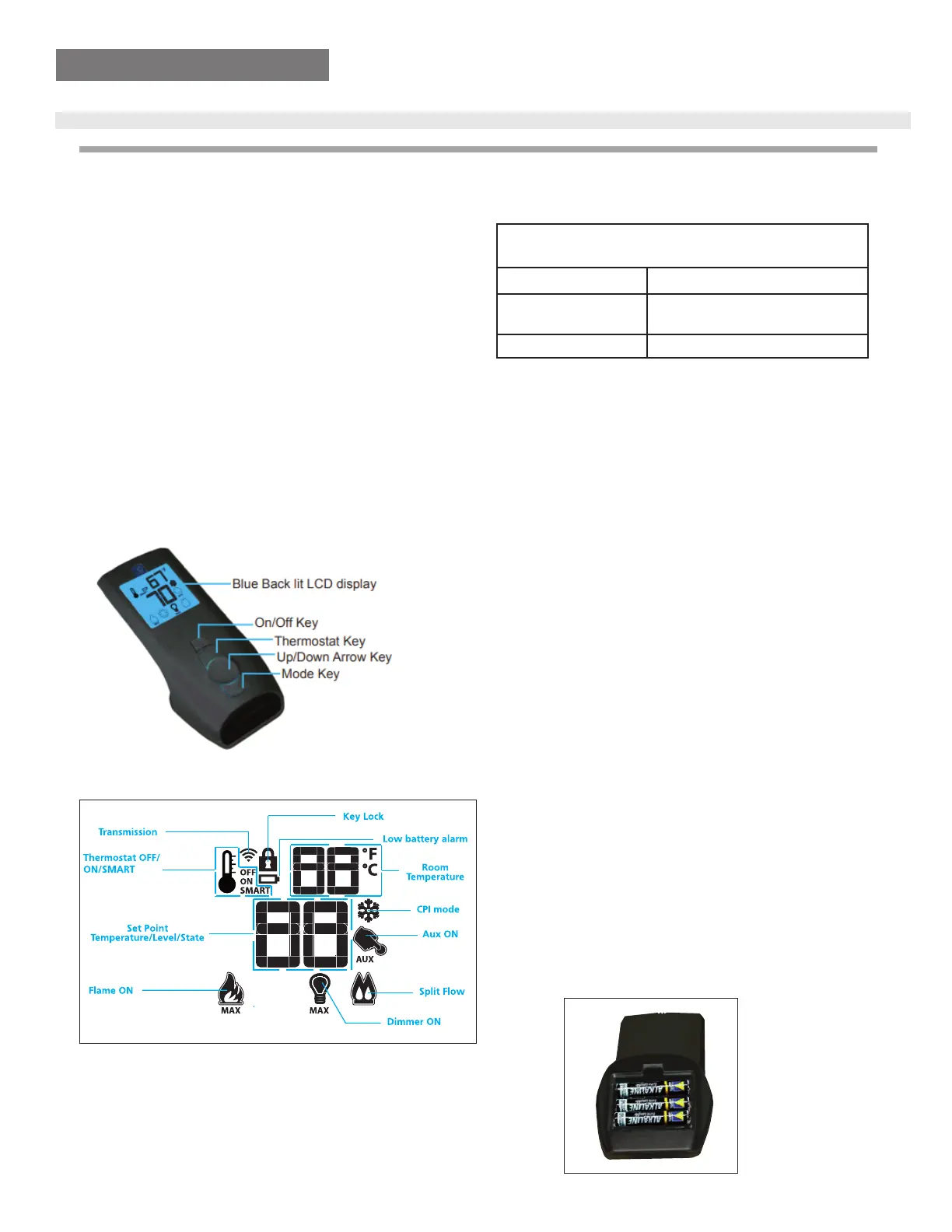
The Profl ame Transmitter uses a streamline design with a simple button
layout and informative LCD display (Fig. 1). A Mode Key is provided to
index between the features and a Thermostat Key is used to turn on/off
or index through Thermostat functions (Fig. 1 & 2). Additionally, a Key
Lock feature is provided (Fig. 22).
Figure 1: Profl ame Transmitter
Figure 2: Transmitter LCD Display
TECHNICAL DATA
REMOTE CONTROL
Supply Voltage 4.5V (three 1.5V AAA batteries)
Ambient temperature
ratings
0 - 50
o
C (32 - 122
o
F)
Radio Frequency 315 MHZ
ATTENTION!
- Turn “OFF” the main gas supply of the appliance during installation or
maintenance of the Receiver device.
- Tu rn “OFF” main gas supply to the appliance prior to removing or rein-
serting the batteries.
- In case of remote control malfunction, turn off the IFC device using the
"ON/OFF" main switch.
- For installation / maintenance, switch off the IFC device removing main
power supply plug.
OPERATING PROCEDURE
Initializing the System fo r the fi rst time
Power the receiver. Activate the procedure of the receiver address pro-
gramming, see the receiver instruction (*). The Receiver will “beep” three
(3) times to indicate that it is ready to synchronize with a Transmitter.
Install the 3 AAA type batteries in the Tr ansmitter battery bay, located on
the base of the Transmitter. (Fig. 3) With the batteries already installed in
the Transmitter, push the On button. The Receiver will “beep” four times to
indicate the Tr ansmitter’s command is accepted and sets to the particular
code of that Transmitter. The system is now initialized.
(*) The receiver may be independent or integral to the IFC hearth ap-
pliance control module. The receiver instruction may not be indepen-
dent when part of the IFC.
Figure 3: Battery Compartment
PROFLAM
E 2
TRANSMI
TTER
USE
ANDINST
AL
L