Section 3
INSTALLATION
3.0 General - This Section outlines the procedures that
are to be followed in order to properly install a FlexPak Plus
controller .
The d-c motor should be installed and wired in accordance
with installation instructions supplied with each drive.
There are certain general warnings and cautions that
should be kept in mind
before planning begins. They
should be considered a general checklist which, if followed,
will minimize installation problems and decrease assembly
time . As a user aid, they are listed here .
DANGER
THIS UNIT SHOULD BE INSTALLED, ADJUSTED
AND SERVICED BY QUALIFIED ELECTRICAL
MAINTENANCE PERSONNEL FAMILIAR WITH
THE CONSTRUCTION AND OPERATION OF THIS
TYPE.OF EQUIPMENT . THEY SHOULD ALSO BE
{' FAMILIAR ' WITH THE POTENTIAL HAZARDS IN-
VOLVED. IF THIS WARNING IS NOT OBSERVED,
PERSONAL INJURY OR EQUIPMENT DAMAGE
MAY RESULT.
DANGER
BE ABSOLUTELY CERTAIN THAT A GROUND
WIRE FROM THE INCOMING A-C POWER LINE IS
PROPERLY CONNECTED TO THE CHASSIS
GROUND TERMINAL PROVIDED . WITHOUT
PROPER GROUNDING, PERSONAL INJURY MAY
OCCUR.
WARNING
THE CONTROLLER REQUIRES A SINGLE-PHASE
POWER SUPPLY THAT PROVIDES EITHER 115
VAC OR
230 VAC AT 50 / 60 HZ. IF CORRECT
VOLTAGE IS NOT AVAILABLE, IT WILL BE
NECESSARY TO INSTALL A TRANSFORMER
BETWEEN THE POWER SUPPLY AND THE CON-
TROLLER . DO NOT OPERATE THE FLEXPAK PLUS
CONTROLLER ON POWER SUPPLIES WITH
AVAILABLE SHORT -CIRCUIT CURRENTS IN
EXCESS OF
5000 AMPERES . DAMAGE TO
EQUIPMENT AND PERSONAL INJURY MAY
OCCUR .
WARNING
THE USER IS RESPONSIBLE FOR CONFORMING
WITH THE NATIONAL ELECTRICAL CODE WITH
RESPECT TO MOTOR. CONTROLLER AND OPER-
ATOR DEVICE INSTALLATION, WIRING AND
START-UP. THE USER IS ALSO RESPONSIBLE
FOR UNDERSTANDING AND APPLYING ALL
OTHER APPLICABLE LOCAL CODES WHICH
GOVERN SUCH PRACTICES AS WIRING PRO-
TECTION, GROUNDING, DISCONNECTS AND
OVERCURRENT PROTECTION.
9
3.1 Layout Guidelines - This Paragraph lists recom-
mended layout procedures common to all FlexPak Plus
controllers .
Guideline 1 -The FlexPak Plus controller is designed as a
panel-mounted unit. It is to be hung within 10° of vertical
with the rear of the Chassis firmly resting against the
mounting surface.
(Do not position the Chassis on a hori-
zontal surface .)
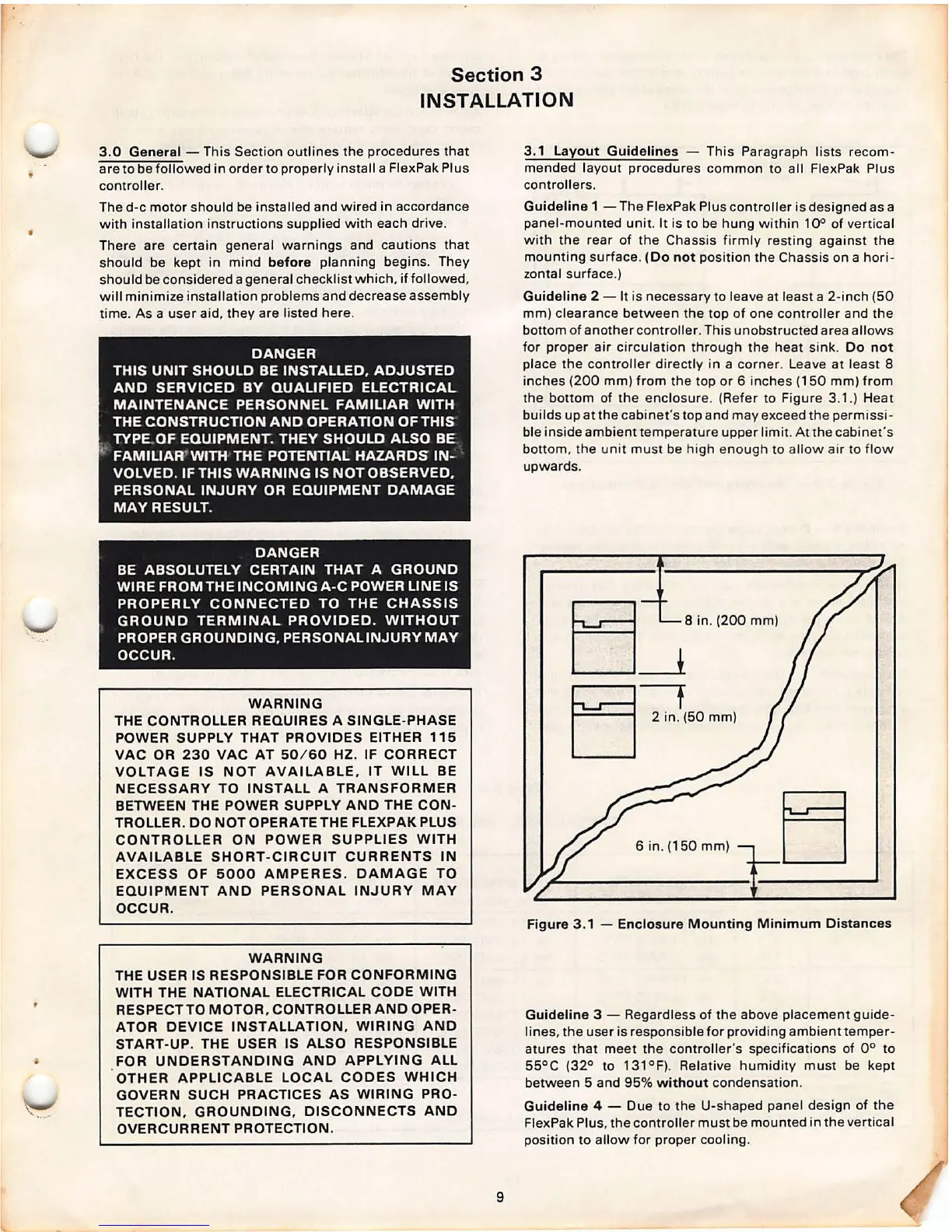
Guideline 2 - It is necessary to leave at least a 2-inch (50
mm) clearance between the top of one controller and the
bottom of another controller . This unobstructed area allows
for proper air circulation through the heat sink .
Do not
place the controller directly in a corner . Leave at least 8
inches (200 mm) from the top or 6 inches (150 mm) from
the bottom of the enclosure . (Refer to Figure 3.1.) Heat
builds up at the cabinet's top and may exceed the permissi-
ble inside ambient temperature upper limit . At the cabinet 's
bottom , the unit mus t be high enough to allow air to flow
upwards .
E:] __ ; ;n. (200 mm(
EJ--:}(50 mm}
6 in . (150 mm)
Figure 3 .1 - Enclosure Mounting Minimum Distances
Guideline 3 -
Regardless of the above placement guide-
lines , the user is responsible for providing ambient temper-
atures that meet the
controller's specifications of 0° to
55°C (32° to 131°F). Relative humid ity must be kept
between 5 and 95%
without condensation .
Guideline 4 - Due to the U-shaped panel design of the
FlexPak Plus, the controller must be mounted in the vertical
position to allow for proper cooling .