JumperJ2
Jumper J1
Figure 5.9 - Jumpers J 1. J2
Step
5 - Since the IR compensation is not used with
tachometer feedback , it is necessary to turn the IR Potent i-
ometer fully CCW. (Refer to Figure 4.1.) If IR compensation
is left in the circuit. erratic operation may result .
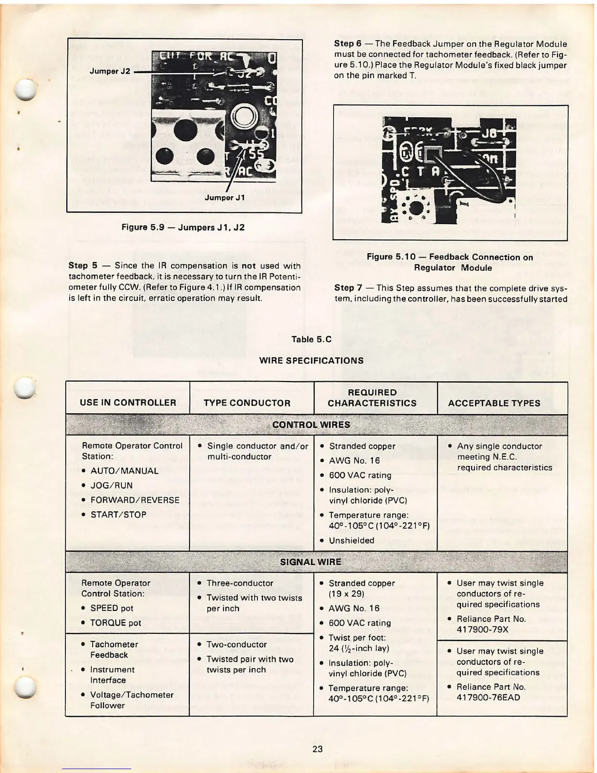
Step 6 - The Feedback Jumper on the Regulator Module
must be connected for tachometer feedback . (Refer to Fig-
ure 5.10 .) Place the Regulator Module 's fixed black jumper
on the pin marked T.
Figure 5. 1 0 - Feedback Connection on
Regulator Module
Step
7 - This Step assumes that the complete drive sys-
tem, including the controller , has been successfully started
Table 5.C
USE IN CONTROLLER
Remote Operator Control
Station :
• AUTO / MANUAL
• JOG / RUN
• FORWARD / REVERSE
• START / STOP
Remote Operator
Control Station :
• SPEED pot
• TORQUE pot
• Tachometer
Feedback
• Instrument
Interface
• Voltage / Tachometer
Follower
WIRE SPECIFICATIONS
TYPE CONDUCTOR
REQUIRED
CHARACTERISTICS
CONTROL WIRES
• Single conductor and/ or
multi -conductor
• Stranded copper
• AWG No. 16
• 600 VAC rating
• Insulation : poly-
vinyl chloride (PVC)
• Temperature range :
40° -105 ° C (104°- 221°F)
• Unshielded
SIGNAL WIRE
• Three -conductor • Stranded copper
• Twisted with two twis ts
(19
X 29)
per inch
• AWG No. 16
• 600 VAC rating
• Two -conductor
• Twist per foot :
24
(1/
2
-inch lay)
• Twisted pair with two
• Insulation : poly-
twists per inch
vinyl chloride (PVC)
• Temperature range :
40° -105° C (104 °- 221
Of)
23
ACCEPTABLE TYPES
• Any single conductor
meeting N.E.C.
required characteristics
• User may twist single
conductors of re-
qui red specifications
• Relianc e Part No.
417900 -79X
• User may twist single
conductors of re-
quired specifications
• Reliance Part
No.
417900- 76EAD