The Kit is designed to accept a line speed input signal of 4 to
10 VDC to obtain maximum speed. The input impedance
between the line speed input terminals 57 and 726 is
approximately 25,000 ohms. The Dancer Potentiometer
will provide up to a 20% trim to the line speed signal.
The user must supply the required lengths of the specified
signal wire. (Refer to Table 5.C.) A Dancer Potentiometer
and an optional Dancer Position Potentiometer are also to
be supplied by the user .
To install the Kit follow these procedures .
Step 1 - Refer to Figure 6.4 and note the heavy border
area in the center of the Regulator Module marked REFER-
ENCE. This is the area where the Dancer Follower Module
is to be mounted. Place the Dancer Follower Module in the
proper orientation so the pin guides on the Module are
aligned over the set of five pins on the Regulator Module.
Lower the Dancer Follower Module so the pins pass
through the pin guides and the mounting spacer seats in
the mounting hole. (It may be necessary to remove a protec -
tive plastic cap from the pins .) Secure the Module with the
supplied screw.
Step 2 - Connect the black pig-tail jumper of the Dancer
Follower Module to pin 319 on the Regulator Module. (Pin
319 is the third pin down in the group of pins marked
TORQUE TAPER.)
Step 3 - Using a twisted pair, connect the external line
speed input to the terminal strip of the Dancer Follower
Module. The plus (+)wire is connected to terminal 726and
the minus (-) wire is connected to terminal 57.
NOTE : Do not strip more than 1/
8
inch (3 mm) of insulation
off the ends of the wires because a short circuit could occur
at any point where the bare wire is exposed. Maintain the
twisted configuration of the two wires as Jong as possible.
Step 4 - Using three twisted wires. connect the user
supplied 5K ohm Dancer Potentiometer to the terminal
strip of the Dancer Follower Module. The speed increase
side of the potentiometer connects to terminal 556 and the
speed decrease side connects to terminal 571. The potenti-
ometer wiper is connected to terminal 919.
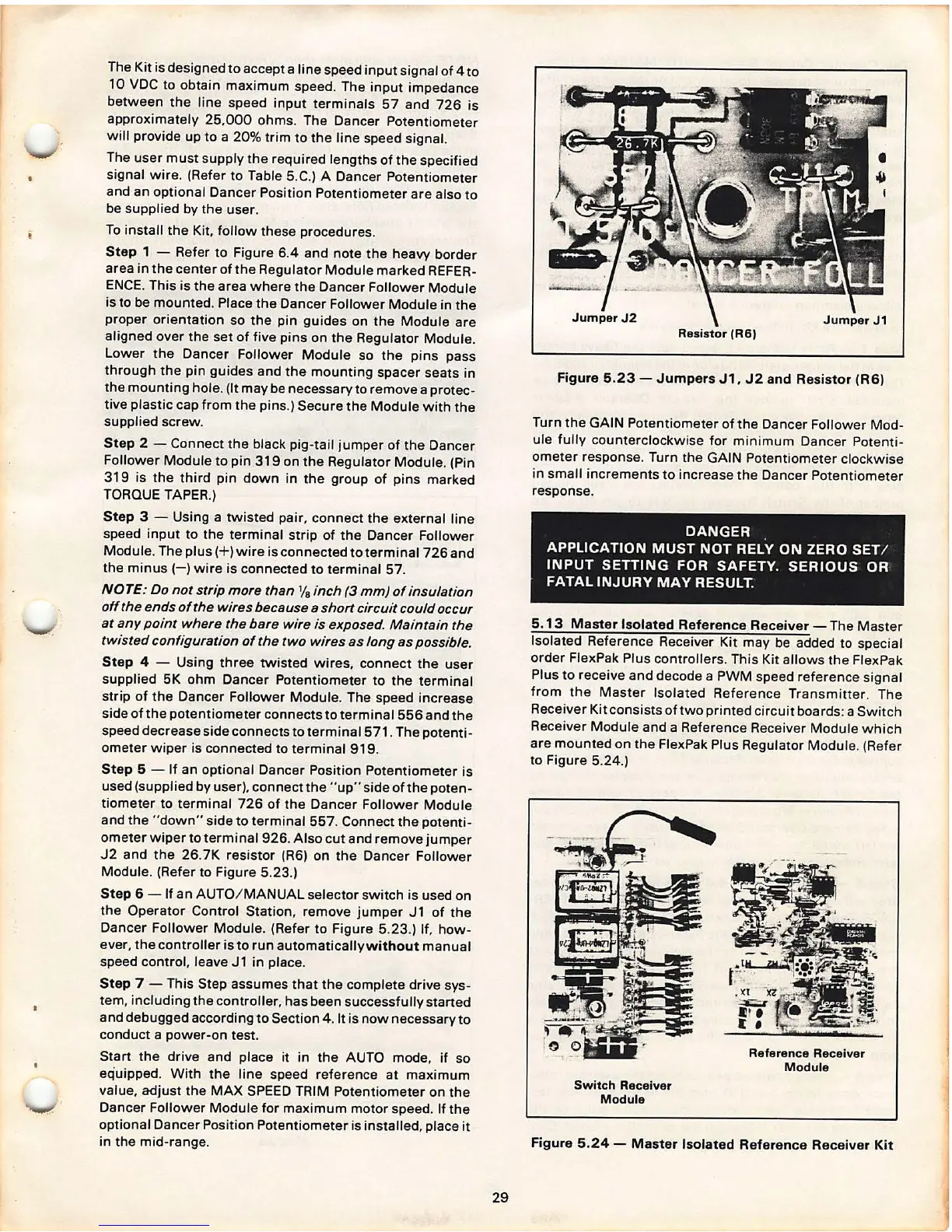
Step 5 - If an optional Dancer Position Potentiometer is
used (supplied by user), connectthe
"up " side of the poten-
tiometer to terminal 726 of the Dancer Follower Module
and the
"down" side to terminal 557 . Connect the potenti-
ometer wiper to terminal 926. Also cut and remove jumper
J2 and the 26.7K resistor (R6) on the Dancer Follower
Module . (Refer to Figure 5.23.)
Step 6 - If an AUTO / MANUAL selector switch is used on
the Operator Control Station, remove jumper J1 of the
Dancer Follower Module. (Refer to Figure 5.23 .) If, how-
ever, the controller is to run automaticallywithout manual
speed control, leave J1 in place .
Step 7 - This Step assumes that the complete drive sys-
tem, including the controller , has been successfully started
and debugged according to Section
4. It is now necessary to
conduct a power-on test.
Start the drive and place it in the AUTO mode, if so
equipped. With the line speed reference at maximum
value , adjust the MAX SPEED TRIM Potentiometer on the
Dancer Follower Module for maximum motor speed. If the
optional Dancer Position Potentiometer is installed, place it
in the mid-range.
29
Resistor (R6)
Figure 5.23 - Jumpers J1. J2 and Resistor (R6)
Turn the GAIN Potentiometer of the Dancer Follower Mod-
ule fully counterclockwise for minimum Dancer Potent i-
ometer response . Turn the GAIN Potentiometer clockwise
in small increments to increase the Dancer Potentiometer
response .
DANGER
APPLICATION MUST NOT
RELY ON ZERO SET/
INPUT SETTING FOR SAFETY. SERIOUS OR
FATAL INJURY MAY RESULT.
5. 13 Master Isolated Reference Receiver -
The Master
Isolated Reference Receiver Kit may be added to special
order FlexPak Plus controllers. This Kit allows the FlexPak
Plus to receive and decode a PWM speed reference signal
from the Master Isolat ed Reference Transmitter . The
Receiver Kit consists of two printed circuit boards: a Switch
Receiver Module and a Reference Receiver Mod ule which
are mounted on the FlexPak Plus Regulator Modul e. (Refer
to Figure 5.24.)
Sw itch Receiver
Module
Reference Receiver
Module
Figure 5.24 - Master Isolated Reference Receiver Kit