up and debugged according to Section 4 thru Paragraph
4.3.1 . It is necessary to carry out a power-on test . Set the
SPEED Potentiometer at approximately 25%of full rotation .
Start the drive . It should run as set. If it accelerates to full
speed, the tachometer is not providing a signal.
Stop the drive, turn off all power , and reverse the leads to
the Tachometer Module 's terminal strip . Repeat the test
with power on in order to confirm that proper feedback
signals are being received by the regulator .
If erratic behavior continues, check the placement of the
two pig-tail jumpers against Steps 3 and 5.
Step 8 - The Maximum and M inimum Speed Potentiome-
ters should now be adjusted to Paragraphs 4 .3.2 and 4.3.3.
Be sure to follow 4.3.4 and 4.3.5 but
do not follow 4 .3.6.
5.6
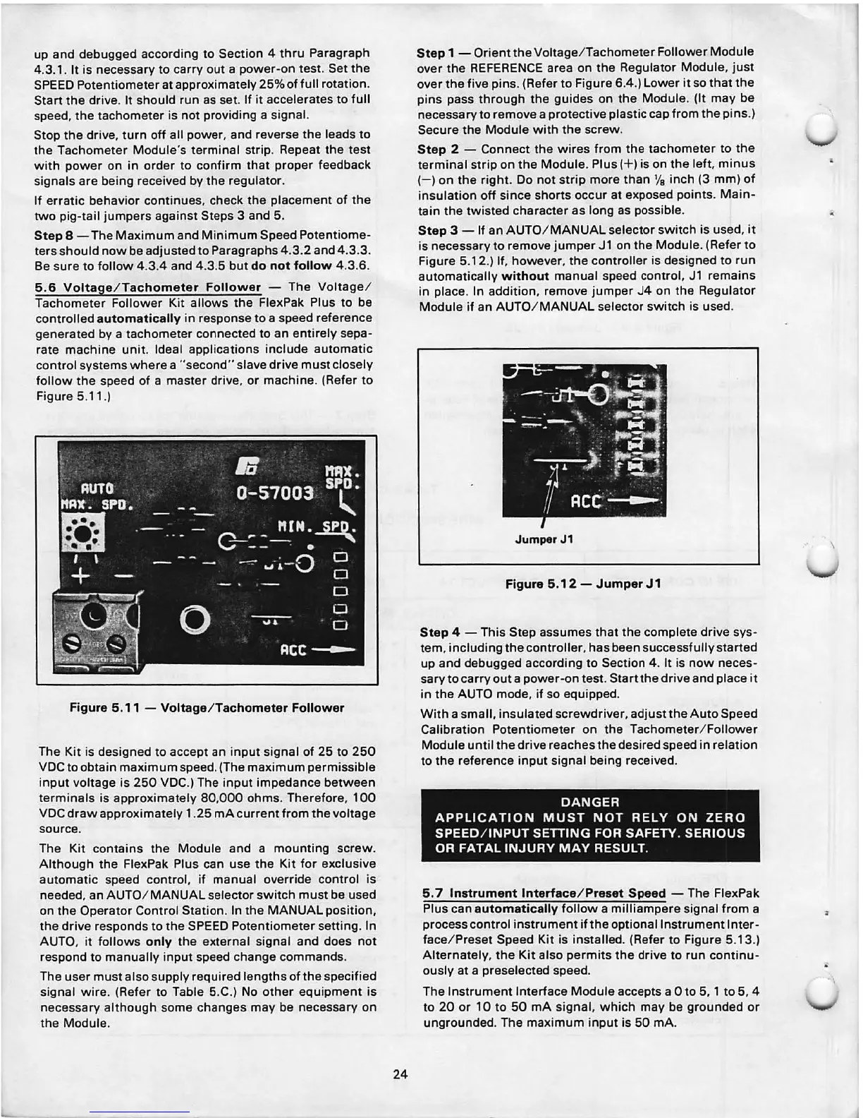
Voltage / Tachometer Follower - The Voltage /
Tachometer Follower Kit allows the FlexPak Plus to be
controlled
automatically in response to a speed reference
generated by a tachometer connected to an entirely sepa-
rate machine unit . Ideal applications include automatic
control systems where a "second" slave drive must closely
follow the speed of a master drive, or machine . (Refer to
Figure 5.11.)
Figure 5.11 - Voltage/Tachometer Follower
The Kit is designed to accept an input signal of 25 to 250
VDC to obtain maximum speed. (The maximum permissible
input voltage is 250 VDC.) The input impedance between
terminals is approximately 80,000 ohms . Therefore , 100
VDC draw approximately 1 .25 mA current from the voltage
source .
The Kit contains the Module and a mounting screw .
Although the FlexPak Plus can use the Kit for exclusive
automatic speed control, if manual override control is
needed , an AUTO/ MANUAL selector switch must be used
on the Operator Control Station. In the MANUAL position,
the drive responds to the SPEED Potentiometer setting. In
AUTO, it follows
only the external signal and does not
respond to manually input speed change commands .
The user must also supply required lengths of the specified
signal wire . (Refer to Table 5.C.) No other equipment is
necessary although some changes may be necessary on
the Module .
24
Step 1 - Orient the Voltage / Tachometer Follower Module
over the REFERENCE area on the Regulator Module, just
over the five pins . (Refer to Figure 6.4 .) Lower it so that the
pins pass through the guides on the Module. (It may be
necessary to remove a protective plastic cap from the pins .)
Secure the Module with the screw .
Step 2 - Connect the wires from the tachometer to the
terminal strip on the Modu le. Plus( + ) is on the left , minus
(-) on the right . Do not strip more than
1/
8
inch (3 mm) of
insulation off since shorts occur at exposed points. Main-
tain the twisted character as long as possible .
Step 3 - If an AUTO / MANUAL selector switch is used, it
is necessary to remove jumper
Jl on the Module . (Refer to
Figure 5.12.) If, however , the controller is designed to run
automatically
without manual speed cont rol, Jl remains
in place . In addition , remove jumper J4 on the Regulator
Module if an AUTO/ MANUAL selector switch is used.
JumperJ1
Figure 5.12 - Jumper J 1
Step 4 - This Step assumes that the complete drive sys-
tem, including the controller, has been successfully started
up and debugged according to Section 4 . It is now neces -
sary to carry out a power-on test. Start the drive and place it
in the AUTO mode , if so equipped .
With a small, insulated screwdriver , adjust the Auto Speed
Calibration Potentiometer on the Tachometer / Follower
Module until the drive reaches the desired speed in relation
to the reference input signal being received .
DANGER
APPLICATION MUST NOT
RE LY ON ZERO
SPEED / INPUT SETTING FOR SAFETY. SERIOUS
OR FATAL INJURY MAY
RESULT.
5. 7 Instrument Interface / Preset Speed - The FlexPak
Plus can
automatically follow a milliampere signal from a
process control instrument if the optional Instrument Inter-
face / Preset Speed Kit is installed . (Refer to Figure 5.13.)
Alternately , the Kit also perm its the drive to run continu-
ously at a preselected speed.
The Instrument Interface Module accepts a Oto 5, 1 to 5, 4
to 20 or 10 to 50 mA signal, which may be grounded or
ungrounded. The maximum input is 50 mA.