2.4 .3 Line Impedance Requirements - The FlexPak Plus
controller must be connected to a short-circuit protec tion
syste m design ed to operat e on plant power supplies with
maximum permissible available symmetrical RMS fault
curren ts of 5000 amperes. (Refer to Table 2.D.)
The Basic Contro lle r does not have an M contactor. An M
contactor is requ ired to provide positive power disconnect.
WARNING
THE USER MUST INSTALL AN M CONTACTOR
THAT HAS A 24
voe COIL WITH A MAXIMUM
CURRENT DRAW OF 150 MILLIAMPS . FOR TIM-
ING, A 200 MICROFARAD CAPACITOR MUST BE
INSTALLED WITH CORRECT POLARITY ACROSS
THE RELAY COIL. THE CONTACTOR ADAPTER
KIT MUST BE INSTALLED WITH THE USER'S M
CONTACTOR . (REFER TO TABLE 5 .A AND
PARAGRAPH 5. 14 .) PERSONAL INJURY MAY
OCCUR IF THIS IS NOT INSTALLED.
WARNING
DO NOT OPERATE
THE FLEXPAK PLUS CON-
TROLLER ON POWER SUPPLIES WITH AVAIL-
ABLE SHORT -CIRCUIT CURRENTS IN EXCESS
OF 5000 AMPERES . DAMAGE TO EQUIPMENT
AND PERSONAL INJURY MAY OCCUR.
2.4 .4 Relay Control Circuit -
The regulator board is set
up for use w ith main cont actors having a coil resistance
greater tha n or equal to 100 ohms . The control logic
sequences the contacto r and the control relay on the regu-
lator so that current fl ow thru the main contactor is never
broken in normal operation by the contacts. Refer to Fig-
ures 6. 1, 6.2 and 6.3.
2.4 . 5 A-C Line Fuse Requirements - A-c line protection
is provided when the A uxi liary Panel is specified. The Basic
FlexPak Controller , however , does not include a-c line pro-
tection . Fused a-c line protection mu st be used . Refer to
Table 2.C for proper fuse sizi ng.
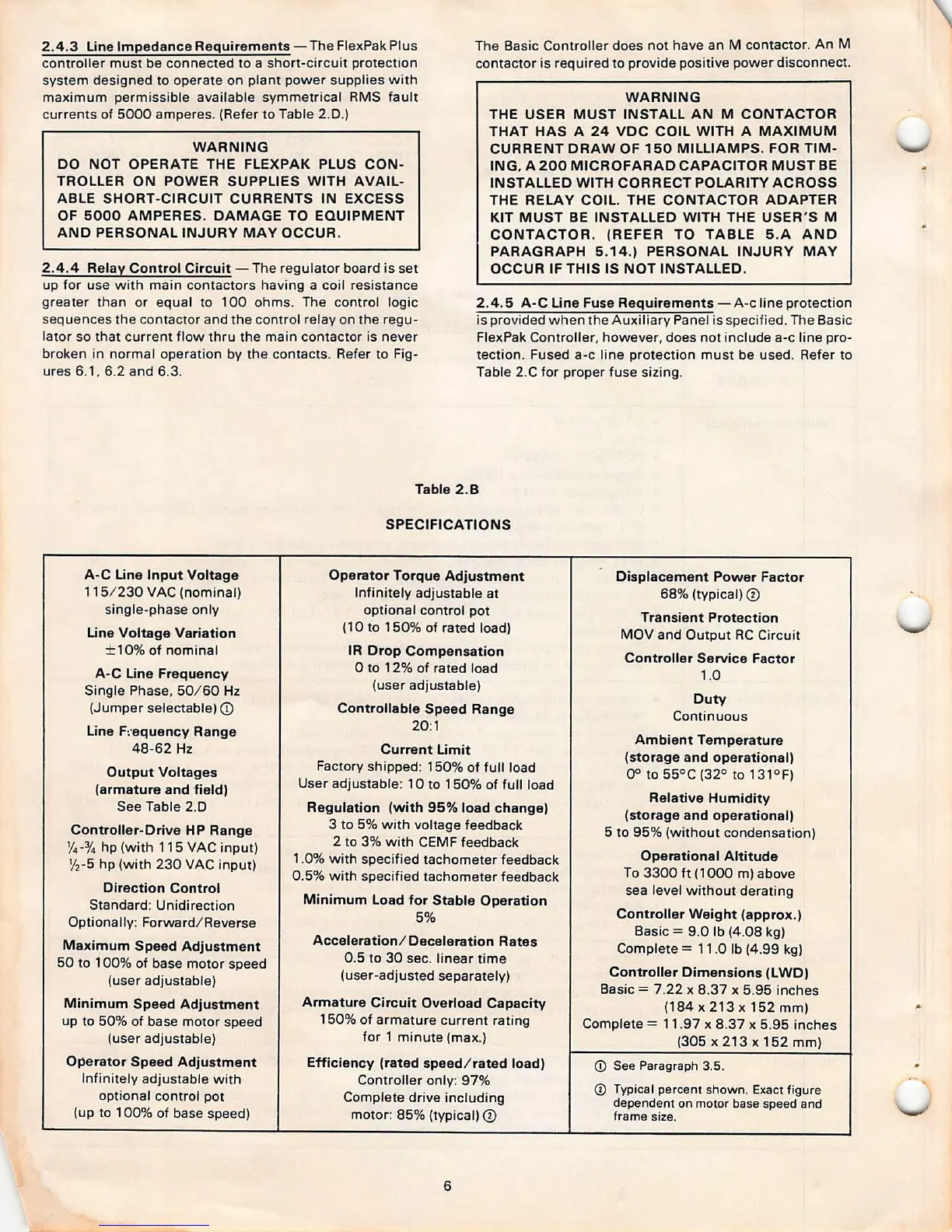
Table 2.B
SPECIFICATIONS
A-C Line Input Voltage
Operator Torque Adjustment
Displacement Power Factor
115/230 VAC (nominal)
Infinitely adjustable at
68% (typical)
CD
single- phase only
optional control pot
Transient Protect ion
Line Voltage Variation
( 10 to 1 50 % of rated load)
MOV and Output RC Circuit
± 10% of nominal
IR Drop Compensation
Controller Service Factor
A-C Line Frequency
0 to 12% of rated load
1 .0
Single Phase, 50/ 60 Hz
(user adjustable)
Duty
(Jumper selectable) CD
Controllable Speed Range
Continuous
Line F:·equency Range
20:1
Ambient Temperature
48-62 Hz
Current Limit
(storage and operational)
Output Voltages
Factory shipped : 150% of full load
00 to 55°C (32° to 131° F)
(armature and field)
User adjustable: 10 to 150 % of full load
See Table 2.D
Regulation (with 95% load change)
Relative Humidity
(storage and operational)
Controller -Drive HP Range
3 to 5% with voltage feedback
5 to 95% (wit hout conde nsation)
Yd'4 hp (with 115 VAC input)
2 to 3% with CEMF feedback
1/
2
-5 hp (with 230 VAC input)
1 .0% with specified tachometer feedback
Operational Altitude
0.5% wit h specified tachometer feedback
To 3300 ft (100 0 m) above
Direction Control
sea level w ithout derating
Standard : Unidirection
Minimum Load for Stable Operation
Optionally: Forward / Reverse
5%
Controller Weight (approx.)
Basic= 9.0 lb (4.08 kg)
Maximum Speed Adjustment
Acceleration / Deceleration Rates
Complete= 1 1 .0 lb (4.99 kg)
50 to 1 00% of base motor speed
0.5 to 30 sec. linear time
(user adjustable)
(user-adjusted separately)
Controller Dimensions (LWD)
Basic= 7.22 x 8.37 x 5.95 inches
Minimum Speed Adjustment
Armature Circuit Overload Capacity
(184 x 213 x 152mm )
up to 50 % of base motor speed
150% of armature current rating
Complete= 11 .97 x 8.37 x 5.95 inches
(user adjustable)
for 1 minute (max.)
(305 x 213 x 152 mm )
Operator Speed Adjustment
Efficiency (rated speed/ rated load)
© See Paragraph 3.5.
Infini tely adjustable with
Controller only : 97%
CD Typical percent shown. Exact figure
optional control pot
Complete drive including
dependent on motor base speed and
(up to 100% of base speed)
motor: 85% (typical)
CD
frame size.
6