Step 3 - Connect the three -wire harness to the Regulator
Module. Locate the letters AUX. M printed on the Module
near a three-pin connector. (Refer to Figure 6.4.) The con-
nector fits on the bayonet pins. Note that -the yellow (39)
wire
must connect with the pin marked YEL 39 on the
Regulator Module .
Step 4 - Route external wiring to the Module 's terminal
block . Do not strip more than
% inch (6 mm) of insulation
from the wires since shorts could occur at exposed points .
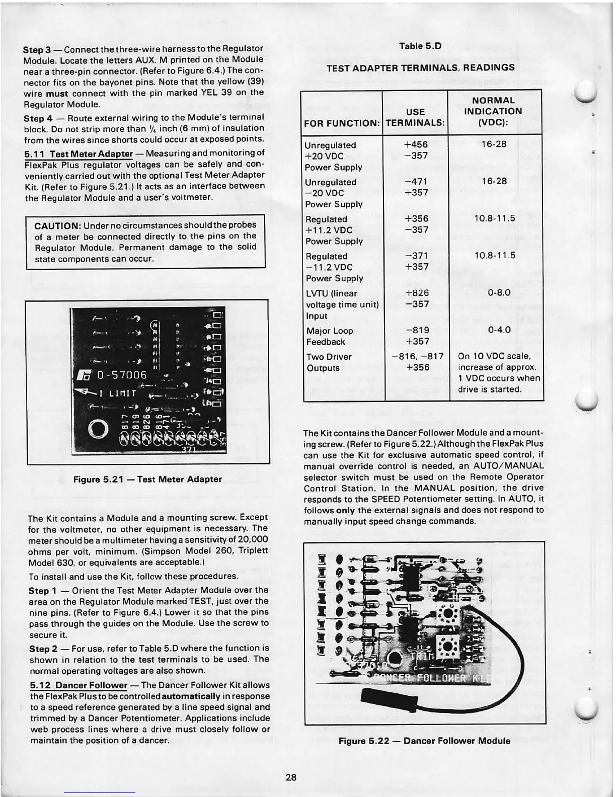
5.11 Test Meter Adapter - Measuring and monitoring of
FlexPak Plus regulator voltages can be safely and con-
veniently carried out with the optional Test Meter Adapter
Kit. (Refer to Figure 5.21.) It acts as an interface between
the Regulator Module and a user's voltmeter .
CAUTION : Undernocircumstancesshouldtheprobes
of a meter be connected directly to the pins on the
Regulator Module . Permanent damage to the solid
state components can occur .
Figure 5.21 -Test Meter Adapter
The Kit contains a Module and a mounting screw . Except
for the voltmeter , no other equipment is necessary. The
meter should be a multimeter having a sensitivity of 20,000
ohms per volt , minimum. (Simpson Model 260 , Triplett
Model 630, or equivalents are acceptable.)
To install and use the Kit, follow these procedures.
Step 1 - Orient the Test Meter Adapter Module over the
area on the Regulator Module marked TEST, just over the
nine pins . (Refer to Figure 6.4.) Lower it so that the pins
pass through the guides on the Module. Use the screw to
secure it.
Step 2 - For use, refer to Table 5.D where the function is
shown in relat ion to the test terminals to be used. The
normal operating voltages are also shown .
5.12 Dancer Follower - The Dancer Follower Kit allows
the FlexPak Plus to be controlled
automatically in response
to a speed reference generated by a line speed signal and
trimmed by a Dancer Potentiometer . Applications include
web process lines where a drive must closely follow or
maintain the position of a dancer .
28
Table 5 .0
TEST ADAPTER TERMINALS , READINGS
NORMAL
USE
INDICATION
FOR FUNCTION:
TERMINALS:
(VDC) :
Unregulated
+ 456
16-28
+20VDC
-357
Power Supply
Unregulated
-471
16-28
-20VDC
+ 357
Power Supply
Regulated
+ 356
10.8-11 .5
+ 11.2VDC
-357
Power Supply
Regulated
-371 10.8-11.5
-11 .2VDC
+ 357
Power Supply
LVTU (linear + 826
0-8 .0
voltage time unit)
-357
Input
Major Loop
-819
0-4 .0
Feedback
+ 357
Two Driver
-816 , -817 On 10 VDC scale,
Outputs
+ 356
increase of appro x.
1
voe occurs when
drive is started .
The Kit contains the Dancer Follower Module and a mount-
ing screw . (Refer to Figure 5.22.)Although the Flex Pak Plus
can use the Kit for exclusive automatic speed control , if
manual override control is needed, an AUTO / MANUAL
selector switch must be used on the Remote Operator
Control Station. In the MANUAL pos ition, the drive
responds to the SPEED Potent iomete r setting . In AUTO , it
follows
only the external signa ls and does not respond to
manually input speed change commands .
Figure 5.22 - Dancer Follower Module