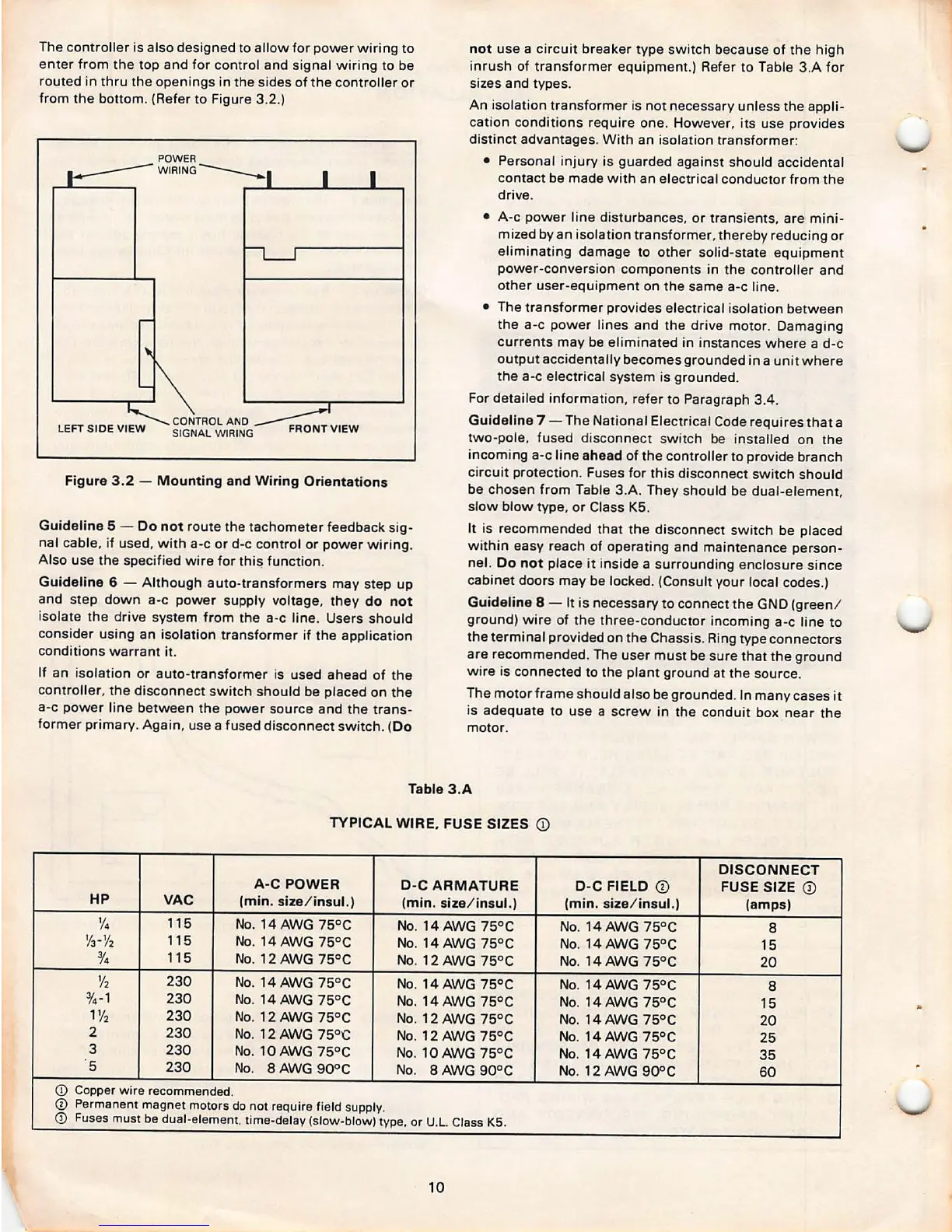
The controller is also designed to allow for power wiring to
enter from the top and for control and signal wiring to be
routed in thru the openings in the sides of the controller or
from the bottom . (Refer to Figure 3.2.)
POWER
WIRING
-----
CONTROL A ND
~
SIGNAL WIRING FRONT VIEW
Figure 3 .2 - Mounting and Wiring Orientations
Guideline
5 - Do not route the tachometer feedback sig-
nal cable, if used, with a-c or d-c control or power wiring.
Also use the specified wire for
thi~ function .
Guideline 6 - Although auto -transform ers may step up
and step down a-c power supply voltage, they
do not
isolate the drive system from the a-c line . Users should
consider using an isolation transformer if the application
conditions warrant it.
If an isolation or auto-transformer is used ahead of the
controller , the disconnect sw itch should be placed on the
a-c power line between the power source and the trans-
former primary . Again , use a fused disconnect switch.
(Do
not
use a circuit breaker type switch because of the high
inrush of transformer equipment.) Refer to Table 3.A for
sizes and types .
An isolation transformer is not necessary unless the appli-
cation conditions require one. However . its use provides
distinct advantages . With an isolation transformer :
• Personal injury is guarded against should accidental
contact be made with an electrical conductor from the
drive.
• A-c power line disturbances , or transients , are mini-
mized by an isolation transformer , thereby reducing or
eliminating damage to other solid-state equipment
power-conversion components in the controller and
other user-equipment on the same a-c line.
• The transformer provides electrical isolation between
the a-c power lines and the drive motor . Damaging
currents may be eliminated in instances where a d-c
output accidentally becomes grounded in a unit where
the a-c electrical system is grounded.
For detailed information. refer to Paragraph 3.4 .
Guideline 7 - The National Electrical Code requires that a
two-pole, fused dis connect swit ch be installed on the
incoming a-c line
ahead of the controller to provide branch
circuit protection . Fuses for this disconnect switch should
be chosen from Table 3.A. They should be dual-element,
slow blow type. or Class K5.
It is recommended that the disconnect switch be placed
within easy reach of operating and maintenance person-
nel.
Do not place it inside a surrounding enclosure since
cabinet doors may be locked . (Consult your local codes .)
Guideline 8 - It is necessary to connect the GND (green /
ground) wire of the three-conductor incoming a-c line to
the terminal provided on the Chassis. Ring type connectors
are recommended . The user must be sure that the ground
wire is connected to the plant ground at the source.
The motor frame should also be grounded . In many cases it
is adequate to use a screw in the conduit box near the
motor .
Table 3.A
TYPICAL WIRE. FUSE SIZES
(D
DISCONNECT
A-C POWER
D-C ARMATURE
D-C FIELD
(D
FUSE SIZE (D
HP
VAC
(min. size / insul.)
(min. size/ insul.) (min . size / insul .)
(amps)
1/4
115
No. 14 AWG 75°C
No. 14 AWG
75°C
No. 14 AWG 75°C
8
1/rY2
115
No. 14 AWG 75°C
No. 14 AWG 75° C No. 14 AWG 75 °C
15
%
115
No. 12AWG75°C
No. 12 AWG 75°C
No. 14 AWG 75°C
20
%
230
No. 14 AWG 75°C
No. 14 AWG 75°C
No. 14 AWG 75°C
8
%- 1
230
No. 14 AWG 75°C
No. 14AWG 75°C
No. 14 AWG 75° C
15
1% 230
No. 12 AWG 75 °C
No. 12 AWG
75°C
No. 14 AWG 75°C
20
2
230
No. 12 AWG
75°C
No. 12 AWG 75°C
No. 14 AWG 75° C
25
3
230
No. 10 AWG 75°C
No. 10 AWG 75 °C
No. 14 AWG 75° C
35
5
230
No.
BAWG 90 °C
No.
BAWG 90°C
No. 12 AWG 90° C
60
CD Copper wire recommended.
CD Permanent magnet motors do not require field supply.
0 Fuses must be dual-element, time-delay (slow-blow) type, or U.L. Class K5.
10