The Kit contains a single Module with a fixed wire harness.
However, its use requires that two other options also be
used:
• Auxiliary Panel
• Reversing Contactor
No other parts are required, and no modifications need be
made to the controller beyond those implied in the above
two options.
To install the Kit, follow these procedures.
Step 1 - Install the Auxiliary Panel and the Reversing
Contactor, as outlined in Paragraphs 5.1 and 5.3.
Step 2 - On the right-hand end of the Auxiliary Mounting
Bracket, orient the Automatic Reversing Module so that the
harness points toward the Regulator Module. (Refer to
Figure 2.2.) Press the four nylon pins firmly into the four
holes in the Auxiliary Mounting Bracket.
Step 3 - Place the harness connector over the Regulator
Module pins marked AUTO REV. (Refer to Figure 6.4.)
Orientation is important: connect the purple (40) wire with
the pin called out as PUR on the Regulator Module.
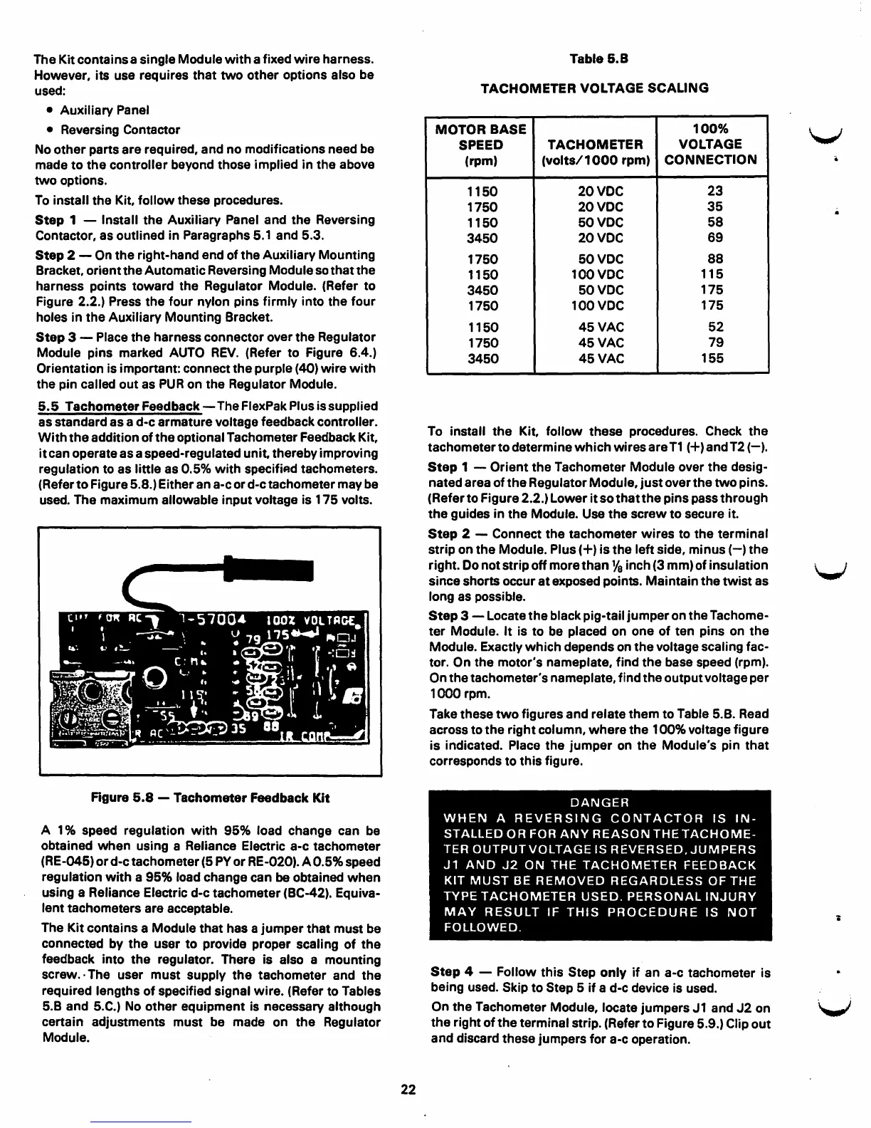
5.5 Tachometer Feedback - The FlexPak Plus is supplied
as standard as a d-c armature voltage feedback controller.
With the addition of the optional Tachometer Feedback Kit,
it can operate as a speed-regulated unit, thereby improving
regulation to as little as 0.5% with specifiAd tachometers.
(Refer to Figure 5.8.) Either an a-c or d-c tachometer may be
used. The maximum allowable input voltage is 175 volts.
Figure 5.8 - Tachometer Feedback Kit
A 1 % speed regulation with 95% load change can be
obtained when using a Reliance Electric a-c tachometer
(RE-045) or d-c tachometer (5 PY or RE-020). A 0.5% speed
regulation with a
95% load change can be obtained when
using a Reliance Electric d-c tachometer (BC-42). Equiva-
lent tachometers are acceptable.
The Kit contains a Module that has a jumper that must be
connected by the user to provide proper scaling of the
feedback into the regulator. There is also a mounting
screw.· The user must supply the tachometer and the
required lengths of specified signal wire. (Refer to Tables
5.B and 5.C.) No other equipment is necessary although
certain adjustments must be made on the Regulator
Module.
22
Table 5.8
TACHOMETER VOLTAGE SCALING
MOTOR
BASE
100%
SPEED
TACHOMETER
VOLTAGE
(rpm)
(volts/ 1000 rpm)
CONNECTION
1150
20VOC
23
1750
20VDC
35
1150
50VDC
58
3450
20VOC
69
1750
50VDC
88
1150
100VDC
115
3450
50VDC
175
1750
100VDC
175
1150
45VAC
52
1750
45VAC
79
3450
45VAC
155
To install the Kit, follow these procedures. Check the
tachometer to determine which wires are T1 (+) and T2 (-).
Step 1 - Orient the Tachometer Module over the desig-
nated area of the Regulator Module, just over the two pins.
(Refer to Figure 2.2.) Lower it so that the pins pass through
the guides in the Module. Use the screw to secure it.
Step 2 - Connect the tachometer wires to the terminal
strip on the Module. Plus(+) is the left side, minus(-) the
right. Do not strip off more than
Ya inch (3 mm) of insulation
since shorts occur at exposed points. Maintain the twist as
long as possible.
Step 3 - Locate the black pig-tail jumper on the Tachome-
ter Module. It is to be placed on one of ten pins on the
Module. Exactly which depends on the voltage scaling fac-
tor. On the motor's nameplate, find the base speed (rpm).
On the tachometer's nameplate, find the output voltage per
1000 rpm.
Take these two figures and relate them to Table 5.B. Read
across to the right column, where the 100% voltage figure
is indicated. Place the jumper on the Module's pin that
corresponds to this figure.
DANGER
WHEN A REVERSING CONTACTOR IS IN-
STALLED OR FOR ANY REASON THE TACHOME-
TER OUTPUT VOLTAGE IS REVERSED.JUMPERS
J1 AND J2 ON THE TACHOMETER FEEDBACK
KIT MUST BE REMOVED REGARDLESS OF THE
TYPE TACHOMETER USED. PERSONAL INJURY
MAY RESULT IF THIS PROCEDURE IS NOT
FOLLOWED.
Step 4 - Follow this Step only if an a-c tachometer is
being used. Skip to Step 6 if a d-c device is used.
On the Tachometer Module, locate jumpers J 1 and J2 on
the right of the terminal strip. (Refer to Figure 5.9.) Clip out
and discard these jumpers for a-c operation.
V
V
V