3.6 HP/ Current Jumper - It is necessary to inspect the
Current Scaling / Horsepower Jumper on the Regulator
Module to be sure that it is connected correctly for a spe-
cific drive motor .
Step 1 - On the drive motor , locate the nameplate. Note
the full-load current .
Step 2 - Or, if current is not shown on the nameplate ,
refer to Table 3.C. Relate the left or center columns in the
tab le with known motor data . Read across to the right
cnlumn marked "Motor Current ." This figure indicates the
proper jumper connection to make on the Module where a
corresponding number is etched .
Table 3.C
HORSEPOWER CALIBRATION
MOTOR HP
MOTOR CURRENT /
115 VAC 230 VAC
PIN CONNECTIONS
1/4
1/2
2.5A
1/3 314
3.7A
Yi
1 5A
7'4
11/2
7.5A
-
2
10A
- 3
15A
- 5
25A
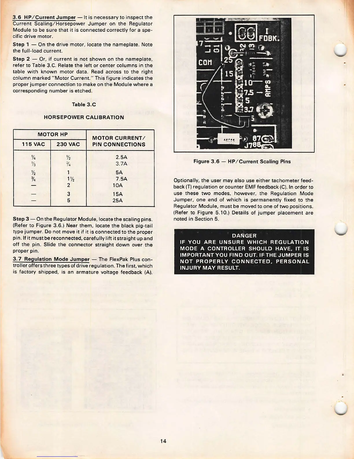
Step
3 - On the Regulator Module , locate the scaling pins .
(Refer to Figure
3.6.) Near them, locate the black pig-tail
type jumper . Do not move it if it is connected to the proper
pin . If it must be reconnected, carefully lift it straight up and
off the pin. Slide the connector straight down over the
proper pin.
3. 7 Regulation Mode Jumper - The FlexPak Plus con-
troller offers three types of drive regulation. The first , which
is factory shipped , is an armature voltage feedback
(A).
14
Figure 3.6 - HP/ Current Scaling Pins
Optionally , the user may also use either tachometer feed-
back (T) regulation or counter EMF feedback
(C). In order to
use these two modes , however, the Regulation Mode
Jumper, one end of which is permanently fixed to the
Regulator Module, must be moved to one of two positions .
(Refer to Figure
5. 10.) Details of jumper placement are
noted in Section 5.
DANGER
IF YOU ARE UNSURE WHICH REGULATION
MODE A CONTROLLER SHOULD HAVE.
IT IS
IMPORTANT YOU FIND OUT. IF THE JUMPER IS
NOT PROPERLY CONNECTED. PERSONAL
INJURY MAY RESULT.