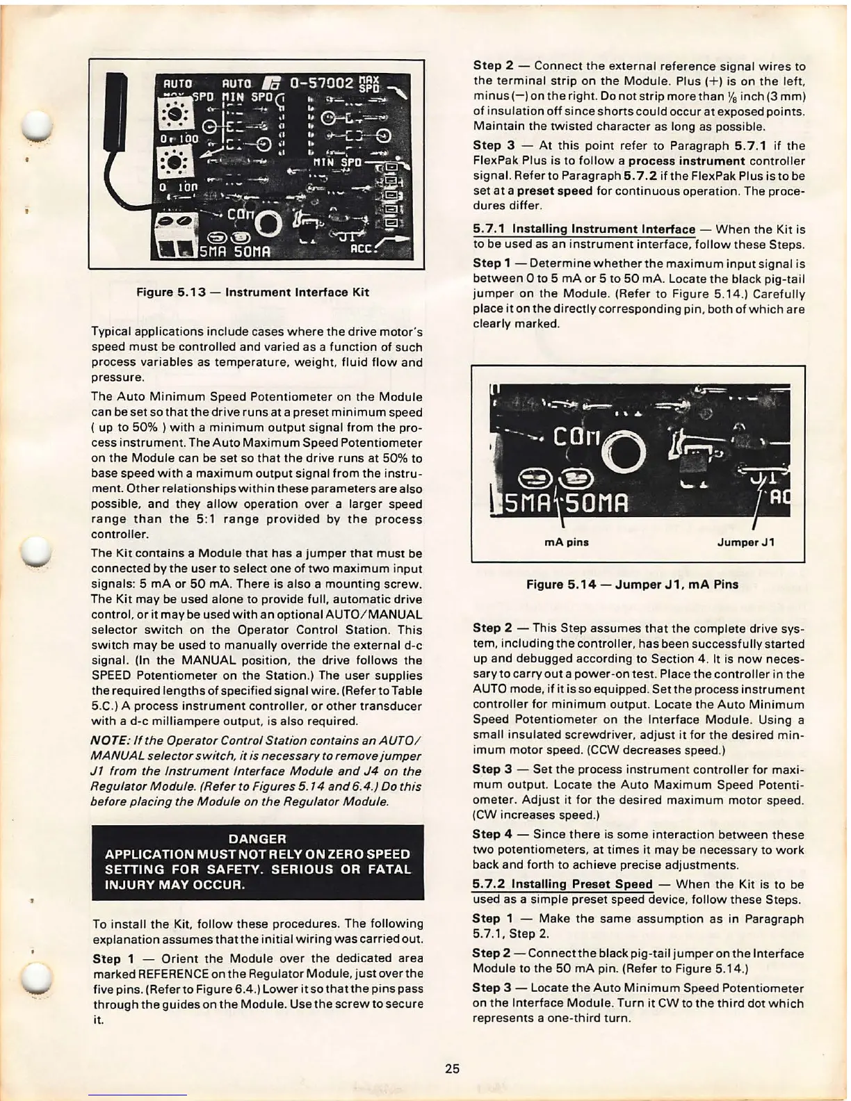
Figure 5.13 - Instrument Interface Kit
Typical applications include cases where the drive motor 's
speed must be controlled and varied as a function of such
process variables as temperature, weight , fluid flow and
pressure .
The Auto Minimum Speed Potentiometer on the Module
can be set so that the drive runs at a preset minimum speed
( up to 50% ) with a minimum output signal from the pro-
cess instrument. The Auto Maximum Speed Potentiometer
on the Module can be set so that the drive runs at 50% to
base speed with a maximum output signal from the instru-
ment . Other relationships within these parameters are also
possible , and they allow operation over a larger speed
range than the 5:1 range proviaed by the process
controller .
The Kit contains a Module that has a jumper that must be
connected by the user to select one of two maximum input
signals : 5 mA or 50 mA. There is also a mounting screw .
The Kit may be used alone to provide full, automatic drive
control, or it may be used with an optional AUTO / MANUAL
selector switch on the Operator Control Station. This
switch may be used to manually override the external d-c
signal. (In the MANUAL position , the drive follows the
SPEED Potentiometer on the Station .) The user supplies
the required lengths of specified signal wire . (Refer to Table
5.C.) A process instrument controller, or other transducer
with a d-c mill iampere output , is also required.
NOTE: If the Operator Control Station contains an AUTO!
MANUAL selector
switch. it is necessary to remove jumper
J1 from the Instrument Interface Module and J4 on the
Regulator Module. (Refer to Figures 5. 14 and 6.4.) Do this
before placing the Module on the Regulator Module .
DANGER
APPLICATION MUST NOT RELY ON ZERO SPEED
SEITING FOR SAFETY. SERIOUS OR FATAL
INJURY MAY OCCUR .
To install the Kit, follow these procedures. The following
explanation assumes thatthe initial wiring was carried out.
Step 1 - Orient the Module over the dedicated area
marked REFERENCE on the Regulator Module, just over the
five pins . (Refer to Figure
6.4.) Lower it so that the pins pass
through the guides on the Module . Use the screw to secure
it.
25
Step 2 - Connect the external reference sig nal wires to
the terminal strip on the Module . Plus( + ) is on the leh,
minus( -) on the right . Do not strip more than
Ya inch (3 mm)
of insulation off since shorts could occur at exposed points.
Maintain the twisted character as long as possible.
Step 3 - At this point refer to Paragraph 5. 7 .1 if the
FlexPak Plus is to follow a
process instrument controller
signal. Refer to Paragraph
5. 7.2 if the FlexPak Plus is to be
set at a
preset speed for continuous operation. The proce-
dures differ.
5.7 .1 Installing Instrument Interface - When the Kit is
to be used as an instrument interface, follow these Steps.
Step 1 - Determine whether the maximum input signal is
between Oto 5 mA or 5 to 50 mA. Locate the black pig-tail
jumper on the Module . (Refer to Figure 5.14 .) Carefully
place it on the directly corresponding pin , both of which are
clearly marked.
mA pins
Jumper J1
Figure 5.14 - Jumper J 1, mA Pins
Step 2 -
This Step assumes that the complete drive sys-
tem, including the controller, has been successf ully started
up and debugged according to Section 4 . It is now neces-
sary to carryout a power-on test . Place the controller in the
AUTO mode , if it is so equipped. Set the process instrument
controller for minimum output . Locate the Auto Minimum
Speed Potentiometer on the Interface Module . Using a
small insulat ed screwdriver , adjust it for the desired min-
imum motor speed . (CCW decreases speed.)
Step 3 - Set the process instrument controller for maxi -
mum output. Locate the Auto Maximum Speed Potenti -
ometer. Adjust it for the desi red maximum motor speed.
(CW increases speed.)
Step 4 - Since there is some interaction between these
two potentiometer s, at times it may be necessary to work
back and forth to achieve precise adjustments.
5. 7.2 Installing Preset Speed - When the Kit is to be
used as a simple preset speed device , follow the se Steps.
Step 1 - Make the same assumption as in Paragraph
5.7.1, Step
2.
Step 2 - Connectthe black pig-tail jumper on the Interface
Module to the 50 mA pin. (Refer to Figure 5.14.)
Step 3 - Locate the Auto Minimum Speed Potentiometer
on the Interfa ce Module . Turn it CW to the third dot which
represents a one-third turn .