' .
The Kit consists of a Module and a mounting screw. No
other equipment is required . However, the SPEED Potenti-
ometer and either the TORQUE Potentiometer or the Cur-
rent Limit Potentiometer on the Regulator Module are used
in conjunction with the two potentiometers on the Module .
To install the Kit and to make initial adjustments , follow
these procedures .
Step 1 - Remove jumpers J7 and JS on the Regulator
Module . (Refer to Figure 6.4 .)
Step 2 - Orient the Module over the area marked TORQUE
TAPER on the Regulator Module , just over the seven pins.
(Refer to Figure 6.4.) Lower it so that the pins pass through
the guides in the Module. Use the mounting screw to
secure it.
Step 3 - On the Regulator Module , adjust the Current
Limit Potentiometer CCW to 100% , or lower. depending on
the application . Remember that it is factory-shipped at
150 %. Dot No. 4 is approximately 100% . (Refer to Figure
4.1 .)
Step 4 - On the Torque Taper Module, turn the CORE
TORQUE Potentio meter completely CCW. The core torque
setting provides a minimum winding torque, or minimum
strip tension, when the winding cycle begins .
Step 5 - On the Torque Taper Module, turn the Torque
Taper Potentiometer completely CW. This assures that
excessive tension will not develop as the first coil or pack-
age is wound.
Step 6 - This Step assumes that the complete drive sys-
tem, including the controller, has been successfully started
up and debugged according to Section
4. It is now neces-
sary to carry out a power-on test . Thread the strip onto the
winder and securely fasten it to the core. Remove all strip
slack before the drive is restarted .
Step 7 - Set the SPEED Potentiometer for a safe maxi-
mum winder speed.
Step 8 - Start the drive . If the strip or web breaks imme-
diately , stop it. Reduce the Current Limit Potentiometer
setting on the Regulator Module . (CCW decreases current,
here torque .)
If the strip does not immediately break, start the process
and allow the winder to begin winding . Accelerate it to
normal running speed. On the Torque Taper Module, adjust
the CORE TORQUE Potentiometer to obtain the desired
strip tension at the beginning of the coil. (CCW decreases,
CW increases .)
Step 9 - As the coil or package increases in diameter,
adjust the TORQUE TAPER Potentiometer on the Torque
Module to maintain proper tension . (CCW increases cur-
rent , here torque .) Adjust in small increments as the diam-
eter grows.
An ammeter in the armature circuit is useful when adjust-
ing both potentiometers on the Module . Observing the
ammeter, which shows current, and the growing coil di-
ameter gives visual confirmation that current (torque) is
increasing too fast or slow in relation to the build-up .
NOTE: Depending on the amount of torque taper desired
and the size of the coil or package being wound, the drive
may go into current limit. However.
at no time should the
Current Limi t Potentiometer on the Regulator Module be
set higher than 100% of the nameplate rating on the motor .
27
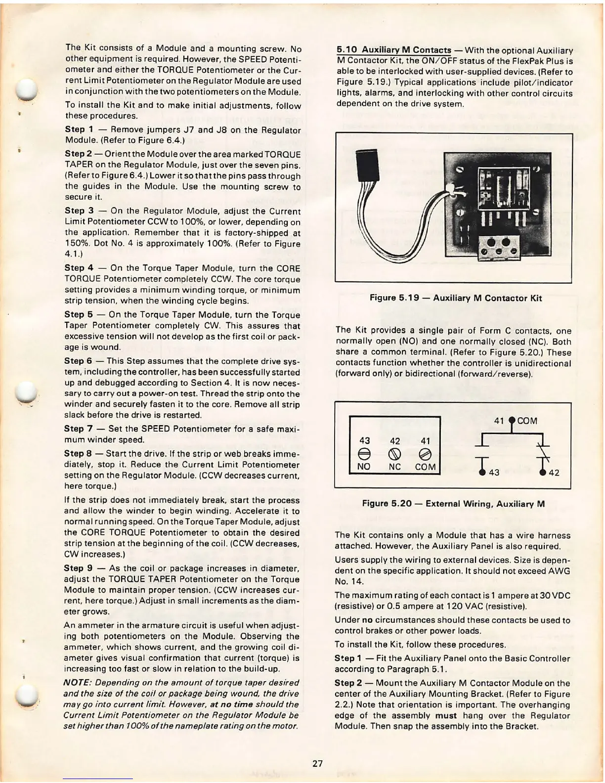
5.10 Auxiliary M Contacts - With the optional Auxiliary
M Contactor Kit, the ON/ OFF status of the FlexPak Plus is
able to be interlocked with user-supplied devices . (Refer to
Figure 5.19.) Typical applications include pilot /i ndicator
lights, alarms , and interlocking with other control circuits
dependent on the drive system.
Figure 5 .19 - Auxiliary M Contactor Kit
The Kit provides a single pair of Form C contacts , one
normally open
(NO) and one normally closed (NC). Both
share a common terminal. (Refer to Figure 5.20.) These
contacts function whether the controller is unidirectional
(forward only) or bidirectional (forward / reverse) .
41 COM
43
42 41
e
© 0
NO
NC COM
Figure 5.20 - External Wiring, Auxiliary M
The Kit contains only a Module that has a wire harness
attached. However , the Auxiliary Panel is also required .
Users supply the wiring to external devices. Size is depen-
dent on the specific application . It should not exceed AWG
No. 14.
The maximum rating of each contact is 1 ampere at 30 VDC
(resistive) or 0 .5 ampere at 120 VAC (resistive).
Under
no circumstances should these contacts be used to
control brakes or other power loads.
To install the Kit. follow these procedures .
S!ep 1 - Fit the Auxiliary Panel onto the Basic Controller
according to Paragraph 5.1 .
Step 2 - Mount the Aux iliary M Contactor Module on the
center of the Auxiliary Mounting Bracket. (Refer to Figure
2.2.) Note that orientation is important. The overhanging
edge of the assembly
must hang over the Regulator
Module . Then snap the assembly into the Bracket.