Step 4 - Place the controller in the AUTO mode, if so
equipped . Locate the Auto Maximum Speed Potentiometer.
Adjust it to obtain the desired preset speed. (CW increases
speed, CCW decreases it.)
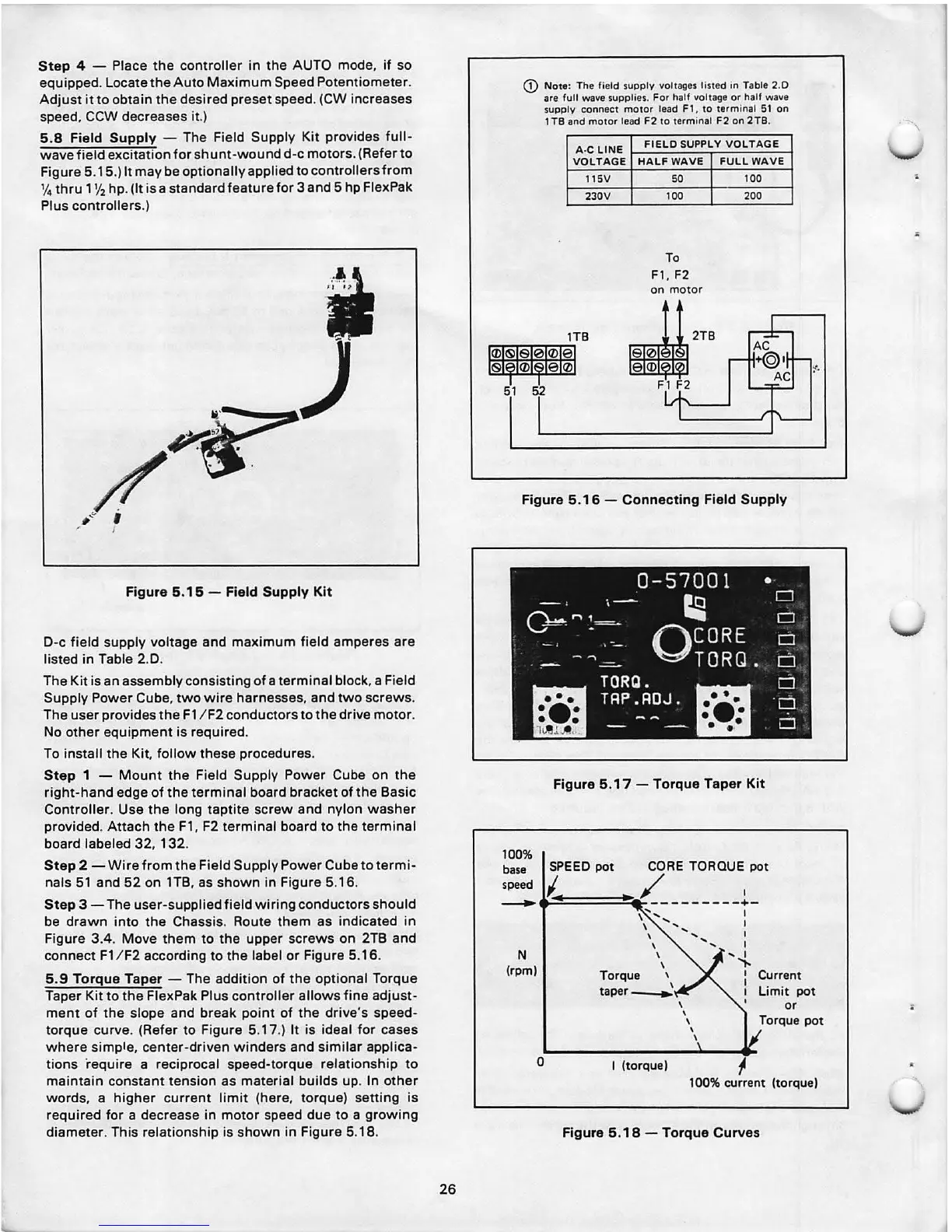
5.8 Field Supply - The Field Supply Kit provides full-
wave field excitation for shunt -wound d-c motors . (Refer to
Figure 5.15.) It may be optionall y applied to controll ers from
% thru 11f2 hp. (It is a standa rd feature for 3 and 5 hp FlexPak
Plus controllers .)
Figure 5.15 - Field Supply Kit
D-c field supply voltage and maximum field amperes are
listed in Table 2.0 .
The Kit is an assembly consisting of a terminal block , a Field
Supply Power Cube, two wire harnesses , and two screws .
The user provides the F1 / F2 conductors to the drive motor .
No other equipment is required.
To install the
Kit. follow these procedures .
Step 1 - Mount the Field Supply Power Cube on the
right-hand edge of the terminal board bracket of the Basic
Controller . Use the long taptite screw and nylon washer
provided . Attach the F1, F2 terminal board to the terminal
board labeled 32, 132 .
Step 2 -Wire from the Field Supply Pow er Cube to termi-
nals 51 and 52 on 1TB, as shown in Figure 5.16.
Step 3 - The user-supplied field wir ing conductors should
be drawn into the Chassis. Route them as indicated in
Figure 3.4. Move them to the upper screws on 2TB and
connect F1 / F2 according to the label or Figure 5.16.
5.9 Torque Taper - The addit ion of the optional Torque
Taper Kit to the FlexPak Plus controller allows fine adjust-
ment of the slope and break point of the drive 's speed-
torque curve . (Refer to Figure 5.17.) It is ideal for cases
whe re simple , center-driven winders and similar applica-
tions require a rec iprocal speed-torque relat ionsh ip to
maintain constant tension as material builds up. In oth er
words , a higher current limit (here , torque) setting is
required for a decrease in motor speed due to a growing
diameter . This relation ship is shown in Figure 5.18.
26
51
G) Not e: The fie ld supp ly voltages liste d in Table 2.0
are full w ave supplies. For half voltage or half wave
supply conn ect mo tor lead Fl , to terminal
51 on
1 TB and moto r lead F2 to term inal F2 on 2 TB.
A·C LINE
FIELD SUPPL Y VOLT AGE
VOLTAGE HALF WAVE FULL WAVE
115V so
100
230V 100 200
To
Fl , F2
on motor
~ 2TB
0
<D
52
Fl F2
Figure 5. 16 - Connecting Field Supply
Figure 5.17 - Torque Taper Kit
100%
base SPEED pot CORE TORQUE pot
~
41/_~===::::!~~ -------t -
N
(rpm)
0
\ ',, I
\ '' I
\ ..............
\
\
Torque ,
taper~
I (torque)
\
\
\
\
\
,
Current
Limit pot
or
Torqu e pot
100% current (torque)
Figure 5.18 - Torque Curves
'
•