t
SYMPTOM
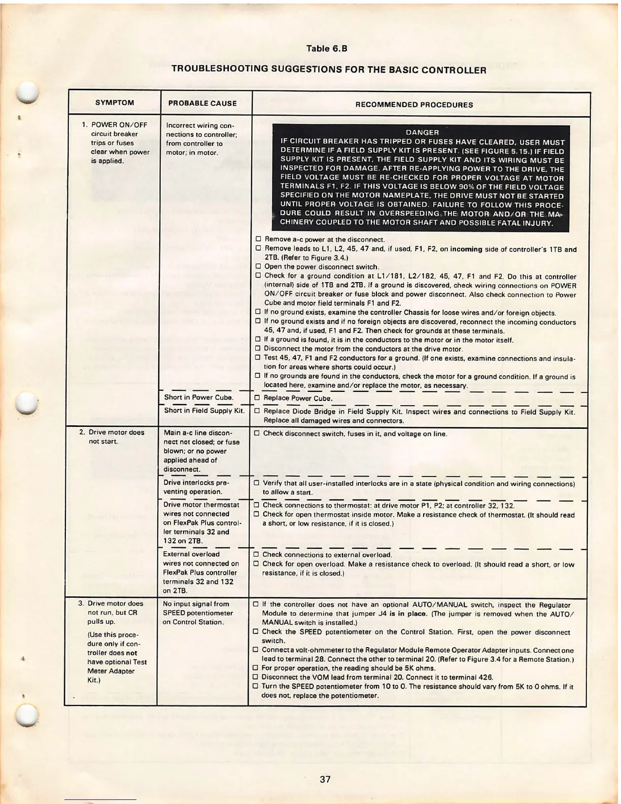
1. POWER ON/ OFF
circuit breaker
trips or fuses
clear when power
is applied .
2. Drive motor does
not start .
3. Drive motor does
not run, but CR
pulls up.
(Use this proce-
dure only if con-
troller does not
have optional Test
Meter Adapter
Kit.)
Table 6.8
TROUBLESHOOTING SUGGESTIONS FOR THE BASIC CONTROLLER
PROBABLE CAUSE
Incorrect wiring con-
nections to controller ;
from controller to
motor ; in motor.
Short in Power Cube.
RECOMMENDED PROCEDURES
DANGER
IF CIRCUIT BREAKER HAS TRIPPED OR FUSES HAVE CLEARED . USER MUST
DETERMINE IF A FIELD SUPPLY KIT IS PRESENT. (SEE FIGURE 5 . 15 .} IF FIELD
SUPPLY KIT IS PRESENT , THE FIELD SUPPLY KIT AND ITS WIRING MUST BE
INSPECTED FOR DAMAGE . AFTER RE-APPLYING POWER TO THE DRIVE, THE
FIELD VOLTAGE MUST BE RE-CHECKED FOR PROPER VOLTAGE AT MOTOR
TERMINALS Fl . F2. IF THIS VOLTAGE IS BELOW 90 % OF THE FIELD VOLTAGE
SPECIFIED ON THE MOTOR NAMEPLATE, THE DRIVE MUST NOT BE STARTED
UNTIL PROPER VOLTAGE IS OBTAINED . FAILURE TO FOLLOW THIS PROCE -
DURE COULD RESULT IN OVERSPEEDING THE MOTOR AND / OR THE MA -
CHINERY COUPLED TO THE MOTOR SHAFT AND POSSIBLE FATAL INJURY.
0 Remove
a-c power at the disconnect.
0 Remove leads to L 1, L2. 45, 47 and, if used, F1, F2, on incoming side of controller's 1TB and
2TB. (Refer to Figure 3.4.)
0 Open the power disconnect switch .
0 Check for a ground condition at ll / 181. L2/ 182, 45, 47, F1 and F2. Do this at controller
(internal) side of 1TB and 2TB. If a ground is discovered, check wiring connections on POWER
ON/ OFF circuit breaker or fuse block and power disconnect . Also check connection to Power
Cube and motor field terminals F1 and F2.
0 If no ground exists. examine the controller Chassis for loose wires and/ or foreign objects .
0 If no ground exists and if no foreign objects are discovered, reconnect the incoming conductors
45, 4 7 and, if used, F 1 and F2. Then check for grounds at these terminals .
0 If a ground is found, it is in the conductors to the motor or in the motor itself .
0 Disconnect the motor from the conductors at the drive motor .
0 Test 45, 47, Fl and F2 conductors for a ground . (If one exists, examine connections and insula-
tion for areas where shorts could occur.}
0 If no grounds are found in the conductors, check the motor for a ground condition . If a ground is
located here, examine and/ or replace the motor , as necessary .
0 Replace Power Cube.
Short in Field Supply Kit.
0 Replace Diode Bridge in Field Supply Kit. Inspect wires and connections to Field Supply Kit .
Main
a-c line discon -
nect not closed ; or fuse
blown ; or no power
applied ahead of
disconnect .
Drive interlock s pre -
venting operation .
Drive motor thermostat
wires not connected
on FlexPak Plus control -
ler terminals 32 and
132 on 2TB.
External overload
wires not connected on
FlexPak Plus controller
terminals 32 and 132
on 2TB.
No input signal from
SPEED potentiometer
on Control Station .
Replace all damaged wires and connectors .
0 Check disconnect switch, fuses in it, and voltage on line.
0 Verify that all user -installed interlocks are in a state (physical condition and wiring connections)
to allow a
start.
0 Check connections to thermostat : at drive motor P1, P2; at controller 32. 132.
0 Check for open thermostat inside motor . Make a resistance check of thermostat. (It should read
a short. or low resistance, if it is closed.}
0 Check connections to external overload .
0 Check for open overload. Make a resistance check to overload . (It should read a short. or low
resistance , if it is closed.}
0 If the controller does not have an optional AUTO/ MANUAL switch . inspect the Regulator
Module to determine that jumper J4 is in place. (The jumper is removed when the AUTO /
MANUAL switch is installed .)
0 Check the SPEED potentiometer on the Control Station. First. open the power disconnect
switch.
0 Connect a volt-ohmmeter to the Regulator Module Remote Operator Adapter inputs . Connect one
lead to terminal 28 . Connect the other to terminal 20. (Refer to Figure 3.4 for a Remote Station .}
0 For proper operation , the reading should be SK ohms .
0 Disconnect the VOM lead from terminal 20. Connect it to terminal 426.
0 Turn the SPEED potentiometer from 10 to 0. The resistance should vary from SK to O ohms. If it
does not. replace the potentiometer .
37