Table 8.8
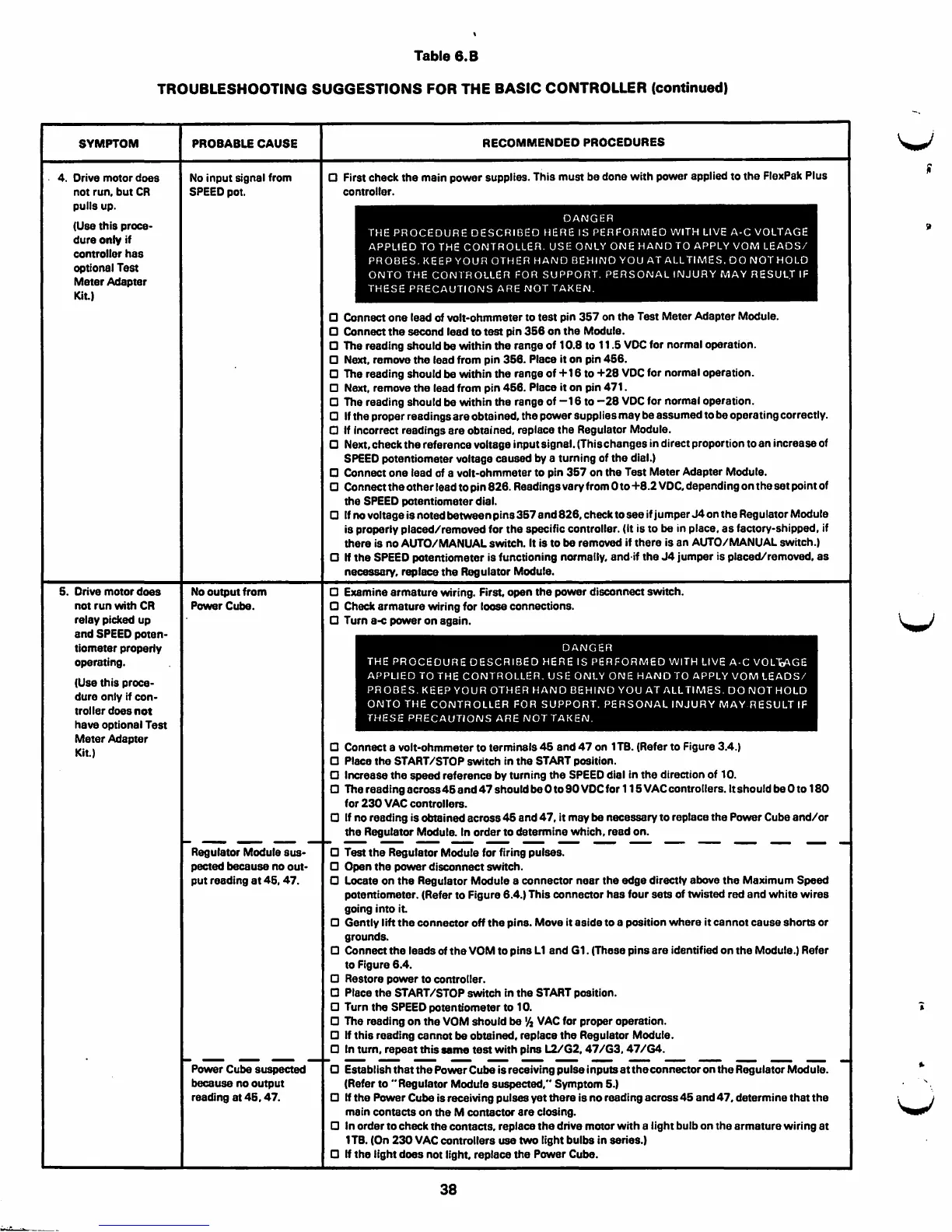
TROUBLESHOOTING SUGGESTIONS FOR THE BASIC CONTROLLER (continued)
SYMPTOM
4. Drive motor does
not run. but CR
pulls up.
-·-·"""'""""'-··-~-
(Use this proce-
dure only if
controller has
optional Test
Meter Adapter
Kit.)
5. Drive motor does
not run with CR
relay picked up
and SPEED poten-
tiometer property
operating.
(Use this proce-
dure only if con-
troller does not
have optional Test
Meter Adapter
Kit)
PROBABLE CAUSE
No input signal from
SPEED pot.
No output from
Power Cube.
Regulator Module sus-
pected because no out-
put reading at 46, 47.
Power Cube suspected
because no output
reading at 46, 47.
RECOMMENDED PROCEDURES
a First check the main power supplies. This must be done with power applied to the FlexPak Plus
controller.
DANGER
THE PROCEDURE DESCRIBED HERE IS PERFORMED WITH LIVE A·C VOLTAGE
APPLIED TO THE CONTROLLER. USE ONLY ONE HAND TO APPLY VOM LEADS/
PROBES. KEEP YOUR 0TH ER HAND BEHIND YOU AT ALL TIMES. 00 NOT HOLD
ONTO THE CONTROLLER FOR SUPPORT. PERSONAL INJURY MAY
RESUL:r IF
THESE PRECAUTIONS ARE NOT TAKEN.
a Connect one lead of volt-ohmmeter to test pin 357 on the Test Meter Adapter Module.
a Connect the second lead to test pin 356 on the Module.
a The reading should be within the range of 10.8 to 11 .5 VOC for normal operation.
a Next, remove the lead from pin 356. Place it on pin 466.
a The reading should be within the range of+ 16 to +28 VOC for normal operation.
a Next, remove the lead from pin 466. Place it on pin 471.
a The reading should be within the range of -16 to -28 voe for normal operation.
a If the proper readings are obtained, the power supplies may be assumed to be operating correctly.
a If incorrect readings are obtained, replace the Regulator Module.
a Next, check the reference voltage input signal. (This changes in direct proportion to an increase of
SPEED potentiometer voltage caused by a turning of the dial.)
a Connect one lead of a volt-ohmmeter to pin 367 on the Test Meter Adapter Module.
a Connect the other lead to pin 826. Readings vary from Oto +8.2 voe, depending on the set point of
the
SPEED potentiometer dial.
a If no voltage is noted between pins 367 and 826, check to see if jumper J4 on the Regulator Module
is properly placed/removed for the specific controller. (It is to be in place, as factory-shipped, if
there is no AUTO/MANUAL switch. It is to be
removed if there is an AUTO/MANUAL switch.)
a If the SPEED potemiometer is functioning normally, and·if the J4 jumper is placed/removed, as
necessary, replace the Regulator Module.
a Examine armature wiring. First, open the power disconnect switch.
a Check armature wiring for loose connections.
a Turn a-c power on again.
DANGER
THE PROCEDURE DESCRIBED HERE IS PERFORMED WITH LIVE
A·C VOL1,.\GE
APPLIED TO THE CONTROLLER. USE ONLY ONE HAND TO APPLY VOM LEADS/
PROBES. KEEP YOUR OTHER HAND BEHIND YOU AT
ALL TIMES. DO NOT HOLD
ONTO THE CONTROLLER FOR SUPPORT. PERSONAL INJURY MAY RESULT IF
THESE PRECAUTIONS ARE NOT TAKEN.
a Connect a volt-ohmmeter to terminals 46 and 47 on 1TB. (Refer to Figure 3.4.)
0 Place the START/STOP switch in the START position.
a Increase the speed reference by turning the SPEED dial in the direction of 10.
a The reading across45 and 47 should be Oto 90 VOC for 115 VAC controllers. ltshould be Oto 180
for 230 VAC controllers.
a If no reading is obtained across 46 and 4 7, it may be necessary to replace the Power Cube and/ or
the Regulator Module. In order to determine which, read on.
------------------------
0 Test the Regulator Module for firing pulses.
a Open the power disconnect switch.
a Locate on the Regulator Module a connector near the edge directly above the Maximum Speed
potemiometer. (Refer to Figure 6.4.) This connector has four sets of twisted red and white wires
going into it.
a Gently lift the connector off the pins. Move it aside to a position where it cannot cause shorts or
grounds.
a Connectthe leads of the VOM to pins L1 and G1. (These pins are identified on the Module.) Refer
to Figure 6.4.
a Restore power to comroller.
0 Place the START/STOP switch in the START position.
a Turn the SPEED potentiometer to 10.
a The reading on the VOM should be 1/
2
VAC for proper operation.
a H this reading cannot be obtained, replace the Regulator Module.
a In turn, repeat this same test with pins L2/G2, 47 /G3, 47 /G4.
------
a Establish that the Power Cube is receiving pulse inputs at the connector on the Regulator Module.
(Refer to "Regulator Module
suspected," Symptom 6.)
a If the Power Cube is receiving pulses yet there is no reading across 45 and 47, determine that the
main contacts on the M contactor are closing.
a In order to check the contacts, replace the drive motor with a light bulb on the armature wiring at
1 TB. (On 230 VAC controllers
use two light bulbs in series.)
a H the light does not light, replace the Power Cube.
38
V
i
V