'
•
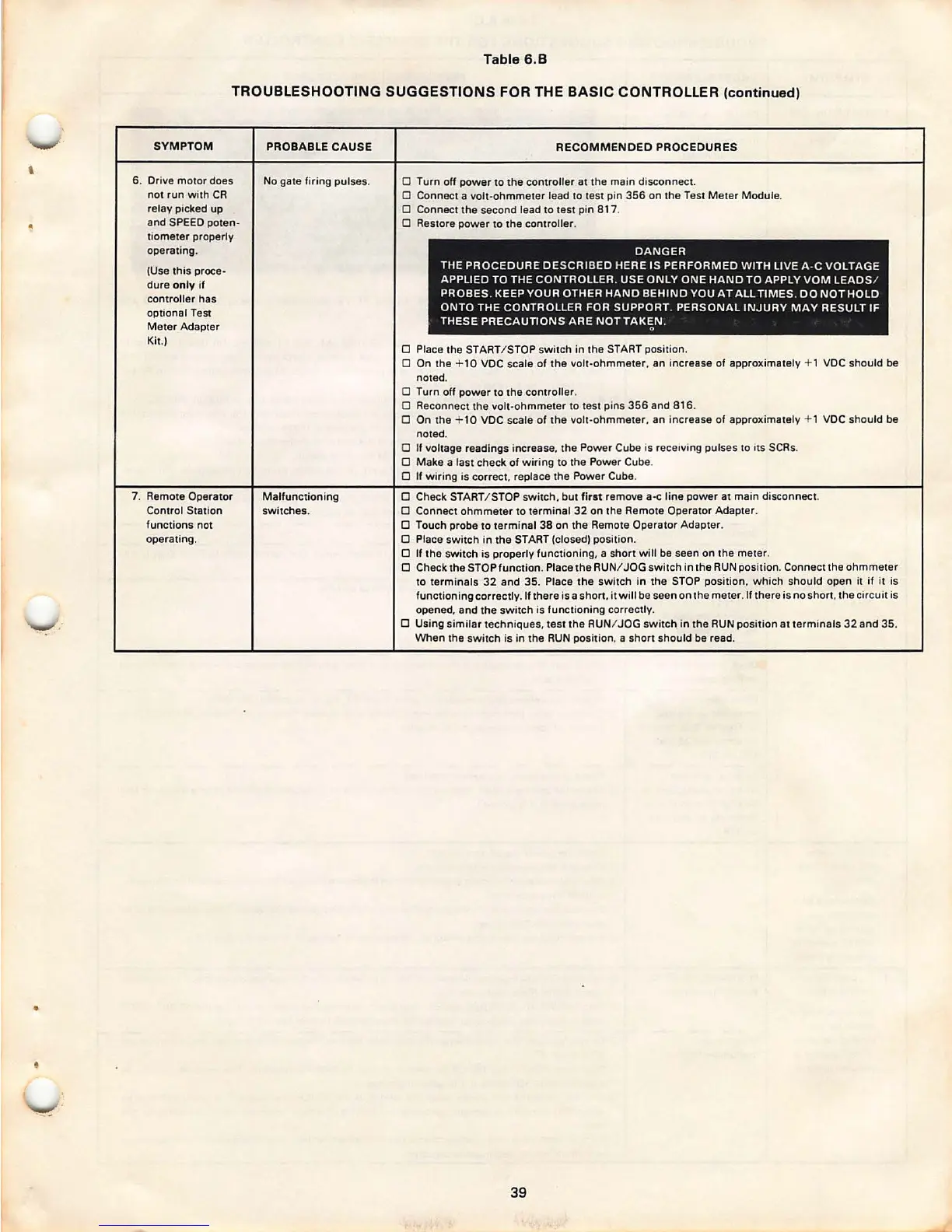
Table 6.B
TROUBLESHOOTING SUGGESTIONS FOR THE
BASIC CONTROLLER (continued)
SYMPTOM
6. Drive motor does
not run with CR
relay picked up
and SPEED pote n-
tiometer properly
operating.
(Use this proce-
dure only if
controller has
optional Test
Meter Adapter
Kit.)
7. Remote Operator
Control Station
function s not
operating.
PROBABLE CAUSE
No gate firing pulses.
Malfunctioning
switches .
RECOMMENDED PROCEDURES
D Turn off power to the controller at the main disconnect.
D Connect a volt-ohmmeter lead to test pin 356 on the Test Met er Module .
D Connect the second lead to test pin 817 .
D Restore power to the controller.
DANGER
THE PROCEDURE DES CRIBED HERE IS PERFORMED WITH LIVE A-C VOLTAGE
APPLIED TO THE CONTROLLER . USE ONLY ONE HAND TO APPLY VOM LEADS /
PROBES. KEEP YOUR OTHER HAND BEHIND YOU A TALL TIMES . DO NOT HOLD
ONTO THE CONTROLLER FOR SUPPORT . PERSONAL INJURY MAY RESULT IF
THESE PRECAUTIONS ARE
NOTTAK~N .
D Place the START/ STOP switch in the START posit ion.
D On the + 10 VDC scale of the volt-ohmmeter, an increase of approximately + 1 VDC should be
noted.
D Turn off power to the controller .
D Reconnect the volt-oh mmeter to test pins 356 and 816 .
D On the + 10 VDC scale of the volt-ohmmeter , an increase of approximately + 1 VDC should be
noted .
D If voltage readings increase, the Power Cube is receiving pulses to ,ts SCRs.
D Make a last check of wiring to the Power Cube.
D If wiring is correct. replace the Power Cube.
D Check START / STOP switch, but
first remove a-c line power at main disconnect.
D Connect ohmmeter to terminal 32 on the Remote Operator Adapter.
D Touch probe to term inal 38 on the Remote Operator Adapter .
D Place switch in the START (closed) position.
D If the switch is properly functioning , a short will be seen on the meter.
D Check the STOP function . Place the RUN/ JOG sw itch in the RUN position . Connect the ohmmete r
to terminals 32 and 35 . Place th e switch in the STOP position , wh ich should open it if it is
functioning correctly. If there isa shon. it will be seen on the mete r. If there is nos hon, the circui t is
opened, and the switch is funct ionin g correc tly .
D Using similar techn iques, test the RUN/ JOG switch in the RUN posit ion at termina ls 32 and 35 .
When the switch is in the RUN positi on, a short should be read .
39