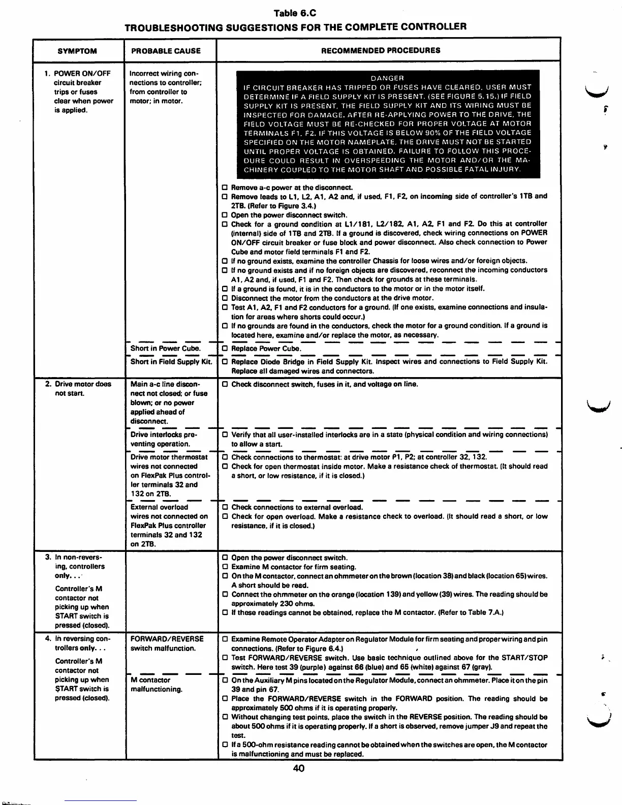
SYMPTOM
1. POWER ON/OFF
circuit breaker
trips or fuses
clear when power
is applied.
2. Drive motor does
not start.
3. In non-revers-
ing, controllers
only ••• ·
Controller's M
contactor not
picking up when
START switch is
pressed (closed,.
4.
In reversing con-
trollers
only . ..
Controller's M
contactor not
picking up when
$TART switch is
pressed
(closed,.
Table 6.C
TROUBLESHOOTING SUGGESTIONS FOR THE COMPLETE CONTROLLER
PROBABLE CAUSE
Incorrect wiring con-
nections to controller;
from controller to
motor; in motor.
Short in Power Cube.
Short in Field Supply Kit.
Main a-c line discon-
nect not closed; or fuse
blown; or no power
applied ahead of
disconnect.
Drive interlocks pre-
venting operation.
Drive motor thermostat
wires not connected
on FlexPak Plus control-
ler terminals 32 and
132on 2TB.
External overload
wires not connected on
FlexPak Plus controller
terminals 32 and 132
on 2TB.
FORVVARD/REVERSE
switch malfunction.
Mcontactor
malfunctioning.
RECOMMENDED PROCEDURES
DANGER
IF CIRCUIT BREAKER HAS TRIPPED OR FUSES HAVE CLEARED. USER MUST
DETERMINE IF A FIELD SUPPLY KIT IS PRESENT. (SEE FIGURE 5.15.) IF FIELD
SUPPLY KIT IS PRESENT. THE FIELD SUPPLY
KIT AND 1TS WIRING MUST OE
INSPECTED FOR DAMAGE. AFTER HE-APPLYING POWER TO THE DRIVE. THE
FIELD VOLTAGE MUST BE RE-CHECKED FOR PROPER VOLTAGE AT MOTOR
TERMINALS F1. F2. IF THIS VOLTAGE IS BELOW 90% OF THE FIELD VOLTAGE
SPECIFIED ON THE MOTOR NAMEPLATE, THE DRIVE MUST NOT BE STARTED
UNTIL PROPER VOLTAGE IS OBTAINED. FAILURE TO FOLLOW THIS PROCE-
DURE COULD RESULT IN OVERSPEEDING THE MOTOR ANO/OR THE MA-
CHINERY COUPLED TO THE MOTOR SHAFT ANO POSSIBLE FATAL INJURY.
a Remove a-c power at the disconnect.
a Remove leads to L1. L2. A1. A2 and, if used, F1, F2. on incoming side of controller's 1TB and
2TB. (Refer to Figure
3.4.,
a Open the power disconnect switch.
a Check for a ground condition at L1/181, L2/182. A1. A2. F1 and F2. Do this at controller
(internal, side of 1TB and 2TB. If a ground is discovered, check wiring connections on POWER
ON/OFF circuit breaker or fuse block and power disconnect. Also check connection to Power
Cube and motor field terminals F1 and F2.
a If no ground exists, examine the controller Chassis for loose wires and/or foreign objects.
a If no ground exists and if no foreign objects are discovered. reconnect the incoming conductors
A 1, A2 and, if used, Fl and F2. Then check for grounds at these terminals.
0 If a ground is found, it is in the conductors to the motor or in the motor itself.
a Disconnect the motor from the conductors at the drive motor.
a Test A 1, A2, F1 and F2 conductors for a ground. (If one exists, examine connections and insula-
tion for areas where shorts could occur.,
a If no grounds are found in the conductors, check the motor for a ground condition. If a ground is
located here,
examine and/or replace the motor, as necessary.
a Replace Power Cube.
a Replace Diode Bridge in Field Supply Kit. Inspect wires and connections to Field Supply Kit.
Replace all damaged wires and connectors.
a Check disconnect switch, fuses in it, and voltage on line.
0 Verify that all user-installed interlocks are in a state (physical condition and wiring connections,
to allow a start.
-------- ----------- --
a Check connections to thermostat: at drive motor P1, P2; at controller 32. 132.
0 Check for open thermostat inside motor. Make a resistance check of thermostat. (It should read
a short, or low resistance, if it is
closed.)
a Check connections to external overload.
0 Check for open overload. Make a resistance check to overload. (It should read a short, or low
resistance, if it is closed.)
a Open the power disconnect switch.
0 Examine M contactor for firm seating.
0 On the M contactor, connect an ohmmeter on the brown (location 38, and black (location 65, wires.
A short should be read.
0 Connect the ohmmeter on the orange (location 139, and yellow (39, wires. The reading should be
approximately 230 ohms.
a If these readings cannot be obtained, replace the M contactor. (Refer to Table 7.A.)
D Examine Remote Operator Adapter on Regulator Module for firm seating and proper wiring and pin
connections. (Refer to Figure 6.4.)
D Test FORVVARO/REVERSE switch. Use basic technique outlined above for the START /STOP
switch. Here test 39 (purple) against 66 (blue, and 65
(white, against 67 (gray,.
a On the Auxiliary M pins located on the Regulator Module, connect an ohmmeter. Place it on the pin
39 and pin 67.
0 Place the FORVVARD/REVERSE switch in the FORVVARD position. The reading should be
approximately 500 ohms if it is operating properly.
a Without changing test points. place the switch in the REVERSE position. The reading should be
about 500 ohms
if it is operating properly. If a short is observed, remove jumper J9 and repeat the
test.
0 If a 500-ohm resistance reading cannot be obtained when the switches are open, the M contactor
is malfunctioning and must be replaced.
40
V
r
V