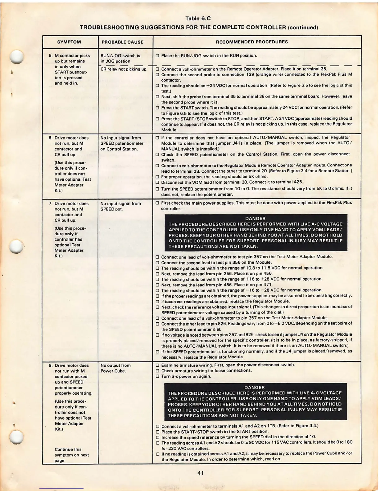
'
Table 6.C
TROUBLESHOOTING SUGGESTIONS FOR THE COMPLETE CONTROLLER (continued)
SYMPTOM
5.
M contactor picks
up but remains
in only when
START pushbut-
ton is pressed
and held in .
6. Drive motor does
not run, but M
contactor and
CR pull up.
(Use this proce-
dure only if con·
troller does not
have optional Test
Meter Adapter
Kit.)
7. Drive motor does
not run. but
M
contacto r and
CR pull up.
(Use this proce -
dure
only if
controller
has
optional Test
Meter Adapter
Kit.)
8. Drive motor does
not run with
M
contactor picked
up and SPEED
potentiometer
properly operat ing.
(Use this proce-
dure only if con-
tro ller does
not
have optional Test
Meter Adapter
Kit.)
Continue this
symptom on next
page
PROBABLE CAUSE
RUN/ JOG switch is
in JOG postion .
CR relay not picking up.
No input signal from
SPEED potentiom eter
on Control Station .
No input signal from
SPEED pot.
No output from
Power Cube.
RECOMMENDED PROCEDURES
D Place the RUN/ JOG switch in the RUN position.
D
Connec~olt -ohmm;;;;; on the Re~ Operator Adapt;:i;lac-;;Tt°on wminal 35 . -- --
0 Connect th e second probe to connection 139 (orange wi re) connected to the FlexPak Plus M
contac tor.
0 The reading should be +24 VDC for normal operation. (Refer to Figure 6.5 to see the logic of this
test.)
D
Next, shift the probe from terminal 35 to terminal 38 on the same termina l board. However , leave
the second probe where it is.
D Press the ST ART switc h. The reading should be approximately 24 VDC for normal operation . (Refer
to Figure 6.5 to see the logic of this test .)
D Press the START / STOP switch to STOP. and then START. A 24 VOC (approximate) reading should
conti nue to appear . If it does not. the CR relay is not picking up. In this case. replace the Regulator
Module.
D If the controller does not have an optional AUTO/ MANUAL switch , inspect the Regulator
Module to determine that jumper J4 i1 in
piece . (The jumper is removed when the AUTO/
MANUAL swi tch is installed.)
D Check the SPEED potentiometer on the Control Station.
First. open the power disconnect
switch .
D Connect a volt-ohmmeter to the Regulator Module Remote Operator Adapter inputs . Connect one
lead to terminal 28. Connect the other to terminal 20. (Refer to Figure 3.4 for a Remote Station .)
D For proper operation. the reading should be 5K ohms .
D Disconnect the VOM lead from terminal 20. Connect it to terminal 426 .
D Turn the SPEED potentiometer from 10 to 0. The resistance should vary from 5K to O ohms. If it
does not, replace the potentiomete r.
D First check the main
power supplie s. This must be done with power applied to the FlexPak Plus
controller .
DANGER
THE PROCEDURE DESCRIBED HERE IS PERFORMED WITH LIVE A ·C VOLTAGE
APPLIED TO THE CONTROLLER. USE ONLY ONE HAND TO APPLY VOM LEADS /
PROBES . KEEP YOUR OTHER HAND BEHIND YOU AT ALL TIMES. DO NOT HOLD
ONTO THE CONTROLLER FOR SUPPORT. PERSONAL INJURY MAY RESULT IF
THESE PRECAUTIONS ARE NOT TAKEN.
D Connect one lead of volt-ohmmeter to test pin 357 on the Test Meter Adapter Module.
D Connect the second lead to test pin 356 on the Module .
D The reading should be within the range of 10.8 to 11.5 VDC for normal operation .
D Next. remove the lead from pin 356 . Place it on pin 456.
D The reading should be within the range of + 16 to + 28 VOC for normal operation.
D
Next, remove the lead from pin 456 . Place it on pin 471 .
D The reading should be within the rang e of -16 to - 28 VOC for normal operation.
D If th e proper reading s are obtained. the power supplie s may be assumed to be operating correctly.
D
If iacorrect readings are obtained, replace the Regulator Module .
D
Next. check the ref erence voltage input signal. (Thi s chang es in direct proportio n to an increase of
SPEED potentiometer voltage caused
by a turning of the dial.)
D Connect one lead of a volt-ohmm eter to pin 357 on the Test Meter Adapter Module .
D Connect the other lead to pin 826 . Readings vary from Oto + 8.2 VDC, depending on the set point of
the SPEED potentiometer dial.
D If no voltage is noted between pins 357 and 826 , check to see if jump er J4 on the Regulator Module
is properly placed/ removed for the specific controller . (It is to be in place, as factory -shipped, if
there is no AUTO/ MANUAL switch . It is to be removed if there is an A UTO/ MANUAL switch.)
D If the SPEED potentiomete r is functioning normally , and if the J4 jumper is placed/ removed, as
necessary, replace the Regulator Module .
D Examine armatur e wiring . First. open the power disconnect switc h.
D Check armature wiring for loose connections.
D Turn a-c power on again .
DANGER
THE PROCEDURE DESCRIBED HERE IS PERFORMED WITH LIVE A -C VOLTAGE
APPLI ED TO THE CONTROLLER. USE ONLY ONE HAND TO APPLY VOM LEADS /
PROBES . KEEP YOUR OTHER HAND BEHIND YOU AT ALL TIMES. DO NOT HOLD
ONTO THE
CONTROLLER FOR SUPPORT. PERSONAL INJURY MAY RESULT IF
THESE PRECAUTIONS ARE NOT TAKEN.
D Connect a volt-ohmmeter to terminals A 1 and A2 on 1 TS. (Refer to Figure 3.4.)
0 Place the START/ STOP switch in the START position .
D Increase the speed reference by turning the SPEED dial in the direction of 10.
O The reading across A 1 andA2shouldbe Oto90VOCfor 115VAC contr ollers. It should be Oto 180
for 230 VAC controller s.
D
If no reading is obtained across A 1 and A2, it may be necessary to replace the Power Cube and/ or
the Regulator Module. In order to determine which , read on.
41