i
i
'--.
2.4 Specifications - The mor e important specifications
for the FlexPak Plus controller are listed in Table 2.8. Refer
also to Table 2.D where other ratings are indicated in rela-
tion to d-c motors of specific horsepower.
However , for optimum 50-Hz operation. it is recommended
that two resistors be removed from the Regulator Module .
(Complete deta ils are given at Paragraph 3.5.) If the resis -
tors are not removed , there is a slight loss of performance .
2.4.1 Line Frequency - The FlexPak Plus controller is
able to operate without modification from a single-phase
power source having a frequency range from 48 to 62 Hz.
2.4.2 Voltage Tolerance - The FlexPak Plus controller
delivers output current and voltage, as listed in Table 2.D. It
will also operate within these regulation specifications
even with incoming line voltag e at
± 10% of nominal.
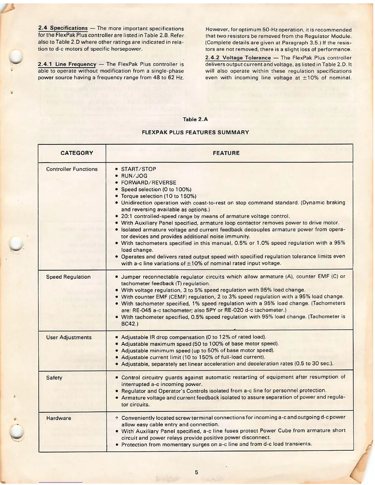
Table 2.A
FLEXPAK PLUS FEATURES SUMMARY
CATEGORY FEATURE
Controller Functions
• ST ART / STOP
• RUN/ JOG
• FOR\NARD/ REVERSE
• Speed selection (0 to 100%)
• Torque selection ( 1 0 to 1 50%)
• Unidirection operat ion with coast-to -rest
or. stop command standard . (Dynamic brak ing
and reversing available as options .)
• 20 :1 controlled-speed range by means of armat ure voltage control.
•
\Nith Auxiliary Panel specified , armature loop contactor removes power to drive motor .
• Isolated armature voltage and current feedback decouples armatu re power from opera-
tor devices and provides additional noise immunity .
•
\Nith tachometers specified in this manual, 0.5% or 1.0% speed regulation with a 95 %
load change .
• Operates and delivers rated output speed with specified regulation tolerance limits even
with a-c line variations of± 10% of nominal rated input voltage .
Speed Regulation
• Jumper reconnectable regulator circuits which allow armature (A), counte r EMF (C) or
tachometer feedback (T) regulation .
•
\Nith voltage regulation, 3 to 5% speed regulation with 95% load change .
•
\Nith counter EMF (CEMF) regulation , 2 to 3% speed regulation with a 95 % load change .
•
\Nith tachometer specified, 1 % speed regulation with a 95% load change . (Tachometer s
are : RE-045 a-c tachometer; also
SPY or RE-020 d-c tachometer .)
•
\Nith tachometer specified, 0.5% speed regulation with 95% load change . (Tachometer is
BC42.)
User Adjustments
• Adjustable IR drop compensation (0 to 12% of rated load).
• Adjustable maximum speed (50 to 100 % of base motor speed).
• Adjustable minimum speed (up to 50% of base motor speed).
• Adjustable current limit (10 to 150 % of full-load current).
• Adjustable, separately set linear acceleration and deceleration rates (0.5 to 30 sec.).
Safety
• Control circuitry guards against automatic restarting of equipme nt after resumption of
interrupted a-c incoming power.
• Regulator and Operator's Controls isolated from a-c line for personnel protection .
• Armature voltage and current feedback isolated to assure separat ion of power and regula-
tor circuits.
Hardware
-:- Conveniently located screw terminal connections for incoming a-c and outgoing d-c power
allow easy cable entry and connection.
•
\Nith · Auxiliary Panel specified, a-c line fuses protect Power Cube from armature short
circuit and power relays provide positive power disconnect .
• Protection from momentary surges on a-c line and from d-c load transients.
5