DANGER
BEFORE WIRING, MAKE SURE THE A-C LINE
DISCONNECT SWITCH IS LOCKED OPEN. EVEN
IF POWER HAS NOT BEEN APPLIED TO THE
INCOMING LINE , THIS PRACTICE ASSURES
PERSONAL SAFETY . IF NO LOCKOUT DEVICE
EXISTS , REMOVE THE FUSES WITH AN INSU -
LATED TOOL AND PLACE A WARNING TAG ON
THE BOX.
WARNING
THE USER MUST INSTALL AN M CONTACTOR
THAT HAS A 24
voe COIL WITH A MAXIMUM
CURRENT DRAW OF 150 MILLIAMPS. FOR TIM-
ING, A 200 MICROFARAD CAPACITOR MUST
BE
INSTALLED WITH CORRECT POLARITY ACROSS
THE RELAY COIL. THE CONTACTOR ADAPTER
KIT MUST BE INSTALLED WITH THE USER'S M
CONTACTOR. (REFER TO TABLE 5.A AND
PARAGRAPH 5.14.) PERSONAL INJURY MAY
OCCUR IF THIS IS NOT INSTALLED.
All interconnecting wire should primarily be sized and
installed in conformance with N.E.C., C.E.C. or local codes .
Refer to the controller and motor nameplates for electrical
data . Typical wire sizes and types are listed in Table 3.A as a
basic guideline. Note that long cable runs may require that
a larger gauge be used to avoid excessive voltage drop . Use
of stranded wire is also recommended . Wire according to
Figure 3.4.
After wiring, examine all terminals to determine that con -
nections are correctly made at
both ends. Confirm wire
identification. Examine the firmness of the connections.
If the Auxiliary Panel is employed , wires to the motor arma -
tur e (A 1 and A2) must be lugged with the provided lugs , or
equivalent , before conn ection to the appropriate relay ter-
minals . Lugs provided will accommodate :
% to 1 Y
2
hp - 12 AWG
1
Y
2
to 3 hp - 10 AWG
5 hp-8AWG
WARNING
DO NOT ALLOW CONDUCTORS TO GROUND ON
THE CHASSIS. CHECK INTEGRITY OF ALL WIRE
INSULATION BEFORE DRAWING. REMOVE
ONLY ENOUGH INSULATION TO MAKE A FIRM
TERMINAL CONNECTION. PERSONAL INJURY
COULD RESULT IF A BARE WIRE TOUCHES THE
CHASSIS.
3.4 Isolation Transformers -
Although an auto-tran s-
former may be required becau se of a-c line voltage levels , it
is unable to provide a number of benefits standard with an
isolat ion transformer .
The general requirements for an isolation tran sformer are :
• Single phase
• 3 to 8% impedance
• Nonregulated
13
• Sinusoidal output
• 50/ 60 Hz, as required
• 150% overload for 1 minute (max .)
Refer also to Table 2.D for specific information on trans-
former sizing requirements . In the 'Tr ansform er" column
at the right, maximum kVA and full -load kVA figures are
listed in relat ion to specific d-c motor hp/ VAC rating s.
Reliance Electr ic offers a number of isolation transformer s
suitable for use with th e FlexPak Plus controller. (Refer to
Table 3.8.)
Table 3.B
RELIANCE ELECTRIC ISOLATION TRANSFORMERS
PRIMARY
SECONDARY ORDER
HP
kVA
VAC VAC NUMBER:
%·Y3
0.75 230 / 460 115
77530-10S
Y4·Y3
0.75 575 115
Special Order
Y2
1.0
230 / 4 60 230 Special Order
Yi
1.0 575 115 Special Order
%
1.5 115 115 77530 -12V
:y4 1.5 575
115 77530-1
lV
%
1.5 230 / 460
115 77530 -lOV
%
1.5 230 / 460
230 Special Ord er
%
1.5
575 230 Special Order
1
2.0 230 / 460
230 77530-BW
1
2.0 575 230 Special Ord er
, Yi
3.0 230 / 460
230 77530 -BX
1
Y2
3.0 575
230 Special Order
2-3 5.0 230 / 460
230
77530 -BY
2-3 5.0 575
230 77530-SY
5
10 .0 230 / 460
230
77530 -BRC
5 10 .0 575
230 77530 -SRC
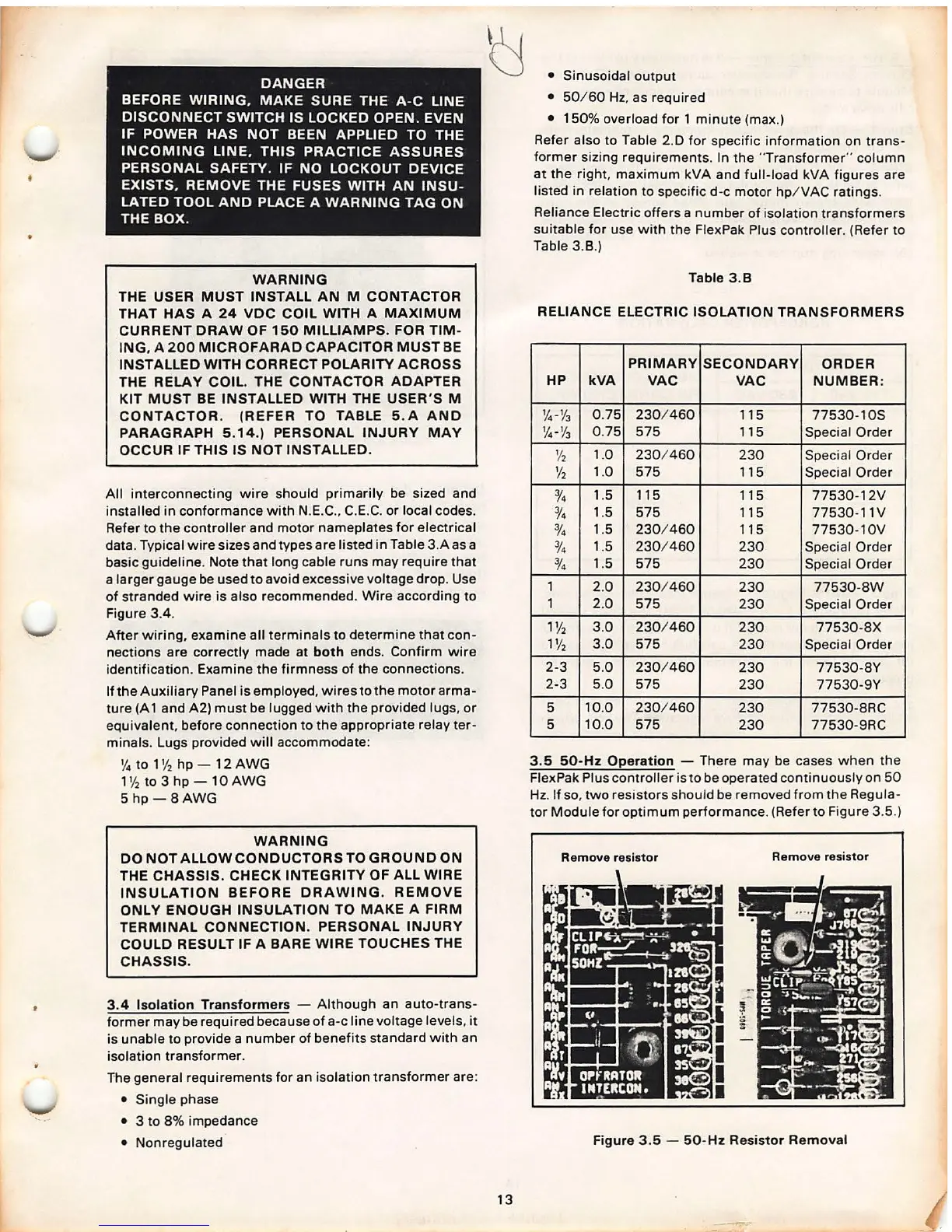
3.5 50-Hz Operation - There may be cases wh en the
Flex Pak Plus controll er is to be operat ed continuou sly on 50
Hz. If so, two resistor s should be remov ed from the Regul a-
tor Module for optimum performan ce. (Refer to Figure 3.5.)
Remove resistor
Remove resistor
Figure 3.5 - 50 -Hz Resistor Removal