"
REMOTE OPERATOR CONTROLS
,--------------------------------,
No
Number
swirch
JOG/RUN
switch
FWD/REV
switch
No
Num ber
START/STOP
switch
426
326
35
67
65
39
32
38
I
I
I
I
I
I
I
I
I
I
I
I
I
I
I
I
I
I
I
I
I
I
L-------------------------------J
0 -C Drive Motor
51 52 32 132
REMOTE OPERATOR
INTERFACE
r----,
I 57
I
1-Phase
Ptant
Power
Pl
P2
.--1-i
32
(RED)
Terminal
Instrument Interface
or
Voltage Follower Kit
132
(ORGI
STOP
RUN
JOG•
TYPICAL OPERATOR SCHEMATIC
24 VAC
+
40
START
_L
r-----1
38 FM 36
~.=-.::.-41.,.._-+--I CR~ ------1
Stat ic
Logic
(BANI I (GANI
35
CR
I FM
65
(ORGI
(BLKI
RM
66
(BLUEi
J9
/'.;\.
L
L_
REV
I
I
I
I
I
I
I
I
FWD
I
I
39
(YELi
67
(GRAY)
1
I
I
I
I
I
I
I
I
I
_J
~----
Notes:
Tachometer Feedback Kit
r------,
I
Process Control
or
Auto
Rtf erenct
Inputs
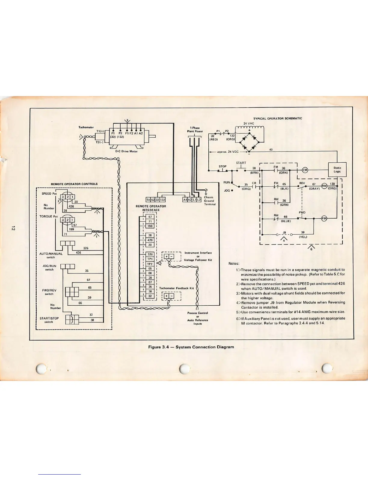
Figure 3.4 - System Connection Diagram
1 > The se signals must be run in a separate magnetic condu it to
minimize th e possibility of noise pickup. (Refer to Table 5.C for
wire specifications .)
2> Remove th e con nection between SPEED pot and terminal 426
when AUTO / MANUAL switch is used .
3> Motors with dual voltage shunt fields should be conn ected for
the higher voltage.
4> Remove jump er J9 from Regu lator Module when Reversing
Contactor is installed.
S> Use convenienc e termina ls for
#14 AWG maximum wire size.
6> 11 Auxiliary Panel is not used , user must supply an appropriate
M con tactor . Refer to Paragraphs 2.4.4 and 5.14 .
/