Guideline 9 -A thermostat is used to guard against motor
overload protection . It is essential to properly connect the
motor thermostat
in series with the Operator's Control
Station
STOP selector switch at connections 32 and 132 .
CAUTION: An external overload device must be con -
nected between terminals 32 and 132. The drive will
not start without it.
Refer to Figure 3.4 where a typical Operator 's Control Sta-
tion schematic is shown .
Guideline 10 - When planning signal or control wire runs.
as listed in Table 5.C, follow these practices:
• Conduits should be steel.
• If these conduits cross 440 VAC conductors , make
sure the cross is at 90 ° .
.....-------r-----------,
I I
I I
I I
I I
0.31 in.
(7.9mml
I
I
11.97 in.
(305mm )
7.22 in.
(183 .4
mml
0.31 in. (7.9 mm)
FRONT VIEW
3.06 in -f-- 3.06 in.
(77.8 mm)
I (77.8 mml
...,.----,----@----+--
6.60 in.
(167 .6
mml
L~-
1
I
---- --
1
MOUNTING HOLE DRILL PLAN
• Do not route signal wires through junctions or termi-
na I boxes that contain non-signal
a-c or d-c
(115/230 / 460 V) wires .
Guideline 11 - Operational altitude above sea level may
not exceed 3300 ft ( 1 000 m ). De rate horsepower 3% for
each 1000
ft (300 m) above this altitude .
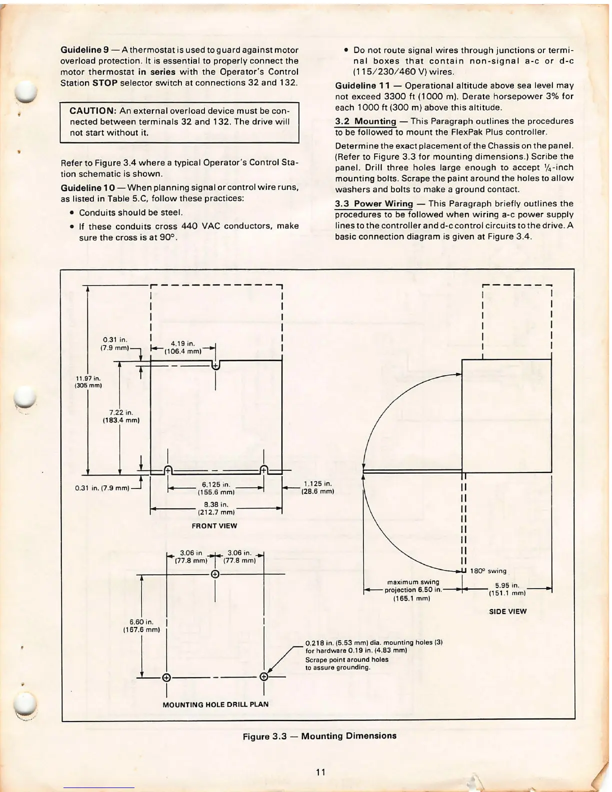
3 .2 Mounting - This Paragraph outlines the procedures
to be followed to mount the FlexPak Plus controller.
Determine the exact placement of the Chassis on the panel.
(Refer to Figure 3.3 for mounting dimensions .) Scribe the
panel. Drill three holes large enough to accept
1
/
4
-inch
mounting bolts . Scrape the paint around the holes to allow
washers and bolts to make a ground contact.
3.3 Power Wiring - This Paragraph briefly outlines the
procedures to be followed when wiring
a-c power supply
lines to the controller and
d-c control circu its to the drive. A
basic connection diagram is given at Figure 3.4 .
maximum swing
projec1ion 6.50 in .
(165.1
mml
0.218 in. (5.53 mml dia. mounting holes (3l
for hardwar e 0.19 in. (4.83 mml
Scrape point around holes
to assure grounding .
II
II
II
II
II
II
II
II
~----- -
. I. 1800 SW~~:
5
in .
(151.1
mml
SIDE VIEW
Figure 3.3 - Mounting Dimensions
11